High speed linear differential amplifier

a technology of differential amplifier and linear amplifier, which is applied in the direction of pulse generator, pulse technique, instruments, etc., can solve the problems of differential amplifier gain that is difficult to vary undetectable, and achieve the effect of expanding the linear rang

Active Publication Date: 2012-05-29
SAMSUNG ELECTRONICS CO LTD
View PDF11 Cites 15 Cited by
  • Summary
  • Abstract
  • Description
  • Claims
  • Application Information

AI Technical Summary

Benefits of technology

[0011]Exemplary embodiments of the inventive concept provide a high speed linear differential amplifier that can output an output signal that linearly changes over an entire swing width range of an input signal regardless of, for example, a manufacturing process or change of temperature. The amplifier employs source degeneration elements to extend the linear range.

Problems solved by technology

However, such amplitude (gain) adjustment circuit elements may cause the gain of the differential amplifier to vary undesirably due to a changes in process, temperature, and swing width of the input signal.

Method used


Image

  • High speed linear differential amplifier
  • High speed linear differential amplifier
  • High speed linear differential amplifier

Examples


Embodiment Construction

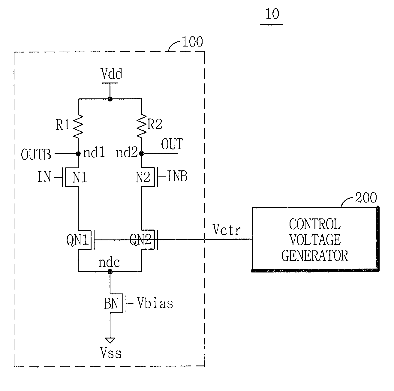
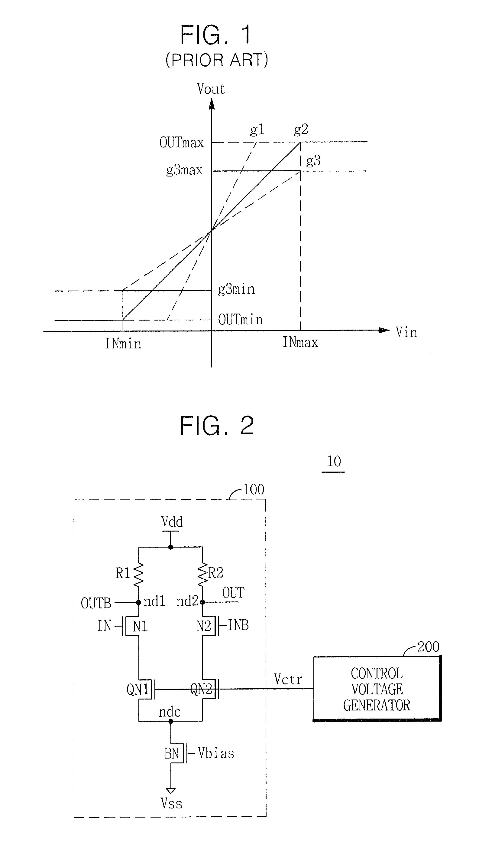
[0036]FIG. 2 is a circuit diagram of a high speed linear differential amplifier 10 according to an exemplary embodiment of the inventive concept. The high speed linear differential amplifier 10 of FIG. 2 includes a differential amplifier 100 that receives an input signal IN and an inverted input signal INB, and that detects and amplifies the voltage difference between the input signal pair IN and INB, and outputs an output signal OUT and an inverted output signal OUTB. The high speed linear differential amplifier 10 of FIG. 2 further includes a control voltage generator 200 that outputs a control voltage Vctr for adjusting the gain of the differential amplifier 100.

[0037]The differential amplifier 100 may include first and second input units that are connected in parallel between a power supply voltage Vdd and a common node ndc and that receive the input signal pair IN and INB, and a driving unit that is connected between the common node ndc and a ground voltage Vss and activates th...


PUM


Abstract

A high speed linear differential amplifier (HSLDA) having automatic gain adjustment to maximize linearity regardless of manufacturing process, changes in temperature, or swing width change of the input signal. The HSLDA comprises a differential amplifier, and a control signal generator including a replica differential amplifier, a reference voltage generator, and a comparator. The comparator outputs a control signal that automatically adjusts the gain of the high speed linear differential amplifier and of the replica differential amplifier. The replica differential amplifier receives predetermined complementary voltages as input signals and outputs a replica output signal to the comparator. The reference voltage generator outputs a voltage to the comparator at which linearity of the output signal of the differential amplifier is maximized. The control signal equalizes the voltage level of the replica output signal and the reference voltage, and controls the gain of the differential amplifier.

Description

PRIORITY STATEMENT[0001]This application claims the benefit of priority, under 35 U.S.C. §119, of Korean Patent Application No. 10-2009-0061166, filed on Jul. 6, 2009, which is hereby incorporated by reference herein in its entirety.BACKGROUND[0002]1. Field of the Inventive Concept[0003]Exemplary embodiments of the inventive concept relate to a high speed linear differential amplifier, and more particularly, to a high speed linear differential amplifier having a gain adjusted by an applied control voltage.[0004]2. Description of Related Art[0005]A differential amplifier is a circuit that detects and amplifies a voltage difference between input signals input to two input terminals and that outputs an amplified voltage. The ratio of a change in voltage difference between output signals to a change in voltage difference between input signals is called the “gain” of the differential amplifier. Differential amplifiers with a large gain widely used, but a differential amplifier with a cha...

Claims


Application Information

Patent Timeline
Patent Type & Authority Patents(United States)
IPC IPC(8): G11C7/00H03L7/00
CPCH03F1/3211H03F3/45179H03F3/45183H03F3/45654H03F2200/453H03F2200/78H03F2203/45382H03F2203/45384H03F2203/45454H03F2203/45466H03F2203/45702H03F1/32H03F3/45
Inventor SOHN, YOUNG-SOOLIM, JEONG-DONPARK, KWANG-IL
Owner SAMSUNG ELECTRONICS CO LTD
Why Eureka
Try Eureka