Automatic vending machine with a plurality of modules and serial bus system

a serial bus system and vending machine technology, applied in the direction of digital transmission, data switching network, instruments, etc., can solve the problems of complex connectors and wiring, difficult addition of modules, and difficult maintenance performance, so as to improve maintenance performance and ensure the effect of reset operation

Inactive Publication Date: 2012-05-29
HITACHI ULSI SYST CO LTD
View PDF23 Cites 2 Cited by
  • Summary
  • Abstract
  • Description
  • Claims
  • Application Information

AI Technical Summary

Benefits of technology

[0012]The present invention has been made in view of the foregoing, and an object of the present invention is to improve reliability of an automatic vending machine and a serial bus system suitable to the same. It is another object of the present invention to improve maintenance performance of the automatic vending machine and the serial bus system suitable to the same. The above-described and other objects and novel characteristics of the present invention will be apparent from the description of the present specification and accompanying drawings.
[0015]In automatic address allocation, by utilizing the AND logic or the OR logic of the control line, the process can be carried out while maintaining high reliability even when there is noise or the like. Moreover, by carrying out this automatic address allocation, the maintenance performance can be improved, for example, in the case where the peripheral modules are added with respect to the communication line. The hard reset is realized by driving the control line to the ‘H’ or ‘L’ level for a certain period of time or more by the main control module and detecting it by the peripheral modules, for example, in the case where the soft reset, which is performed by transmitting a reset command via the signal line, does not work. Therefore, the reset operation can be reliably realized even when there is noise or the like, and reliability such as fail safe can be improved.
[0017]The effects obtained by typical aspects of the invention disclosed in the present application can be described as realization of an automatic vending machine and a serial bus system which are highly reliable. Moreover, an automatic vending machine and a serial bus system having high maintenance performance can be realized.

Problems solved by technology

Specifically, complexity of wiring and overlapping of noise has been problematic when an alternating-current wiring for an electromagnetic solenoid and a direct-current wiring for a sold-out detection switch are independently provided in a vending mechanism; and this problem is solved by arranging the circuit configuration in the vending mechanism.
In this case, when the configuration in which the modules are connected to a unit main body (main control unit) in parallel is employed as disclosed in Patent Document 1, connectors and wiring become complex, and, depending on the number of the connectors, adding modules may become difficult.
However, in this case, human resources having a certain level of skills have to be ensured, and there is also the possibility of human error, etc.
On the other hand, it is known that the noise environment is bad in an automatic vending machine as described in Patent Document 3.
The serial bus in the automatic vending machine has sometimes a wiring length of, for example, several tens of meters, and it is correspondingly readily affected by external noise.
However, the reset operation by the serial bus becomes difficult in the situation in which, for example, a certain module goes out of control and the module exclusively continues output to the serial bus.
Therefore, since connecting the contents display unit MDa or the like that requires a high processing speed to such SB is difficult, as a countermeasure therefor, separately connecting it to RS-232C is conceivable.
However, in such a configuration, when the peripheral modules MD that require high processing speeds are added later as described above, the number of the ports of RS-232C will be a bottleneck.
However, also in this case, as described above, the problems of reliability that accompanies the reset operation and the maintenance performance not dependent on manpower cannot be solved.

Method used


Image

  • Automatic vending machine with a plurality of modules and serial bus system
  • Automatic vending machine with a plurality of modules and serial bus system
  • Automatic vending machine with a plurality of modules and serial bus system

Examples


first embodiment

[0040](First Embodiment)

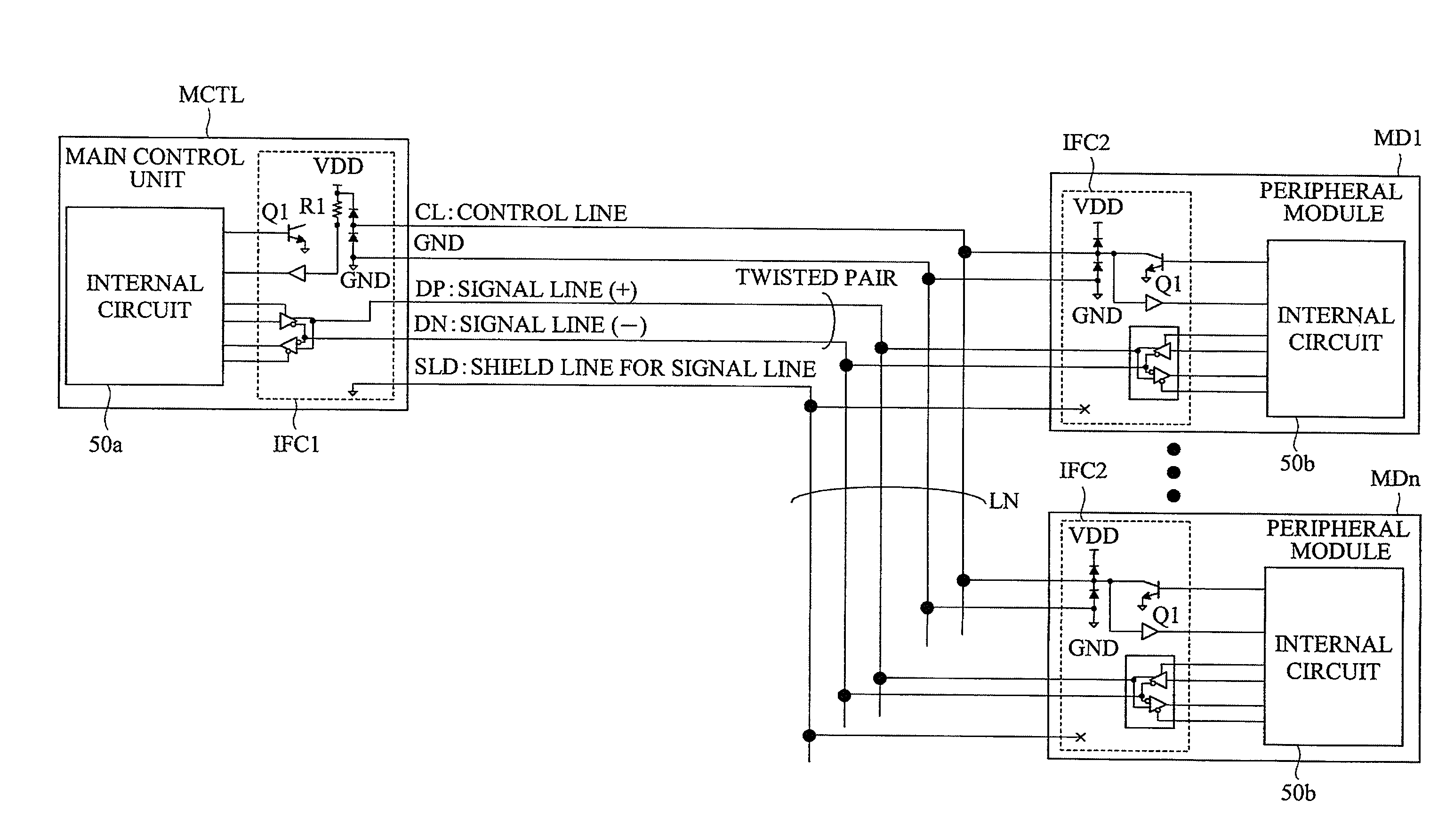
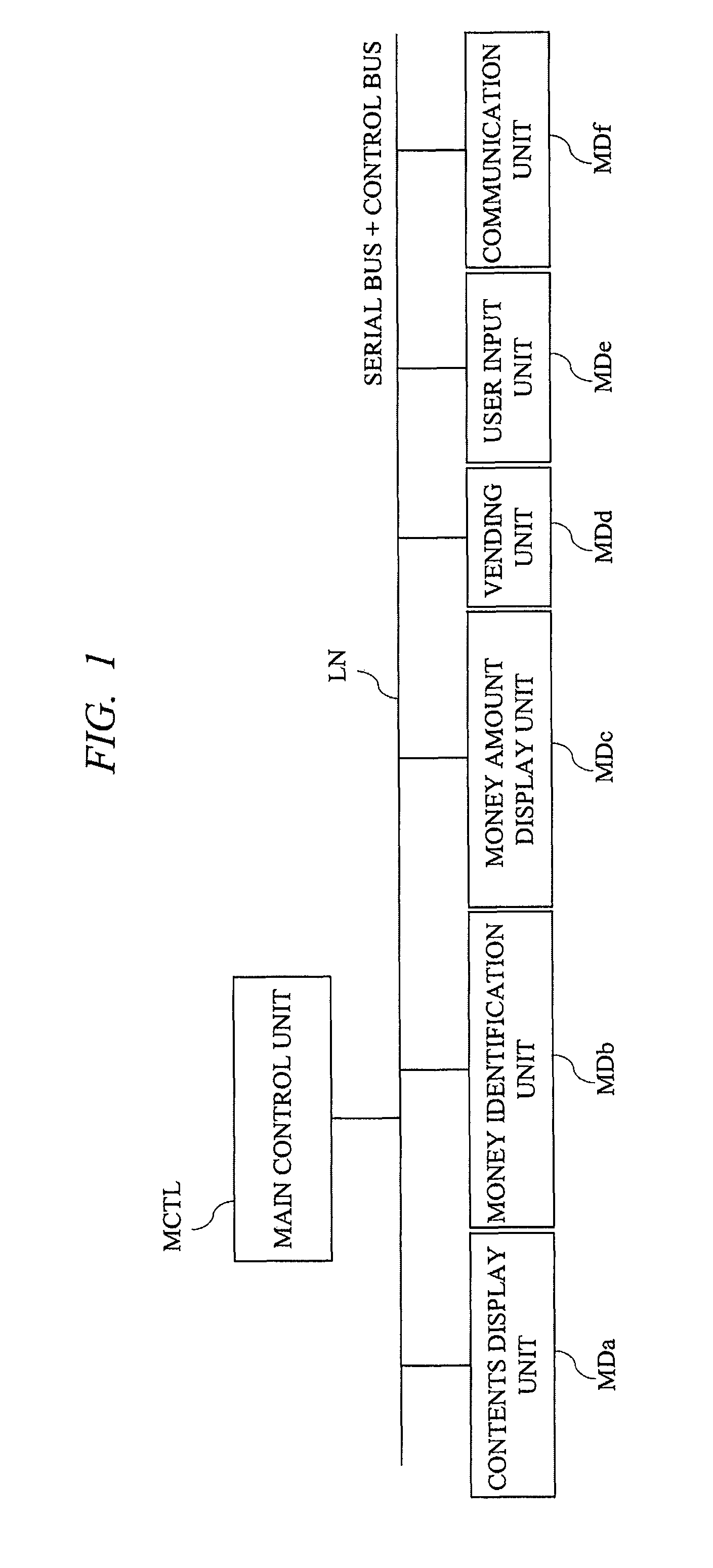
[0041]FIG. 1 is a block diagram showing an example of a configuration of an automatic vending machine according to a first embodiment of the present invention. The automatic vending machine shown in FIG. 1 has a configuration in which a main control unit MCTL and a plurality of peripheral modules MD are connected on a communication line LN. And, it is a feature that the peripheral modules MD connected to the LN includes, for example, a contents display unit MDa and a communication unit MDf in addition to a money identifying unit MDb, a money amount display unit MDc, a vending unit MDd, a user input unit MDe, etc.

[0042]The money identifying unit MDb has a function of identifying the money inserted into the automatic vending machine, and the money amount display unit MDc has a function of displaying the identified money. The user input unit MDe has a function of controlling user interfaces typified by buttons of the automatic vending machine, and the vending un...

second embodiment

[0073](Second Embodiment)

[0074]In a second embodiment, a configuration example which is a modification of the wiring topology of FIG. 2 described in the first embodiment will be described. In addition, a detailed configuration example including the internal circuits of the main control unit and the peripheral module will be also described.

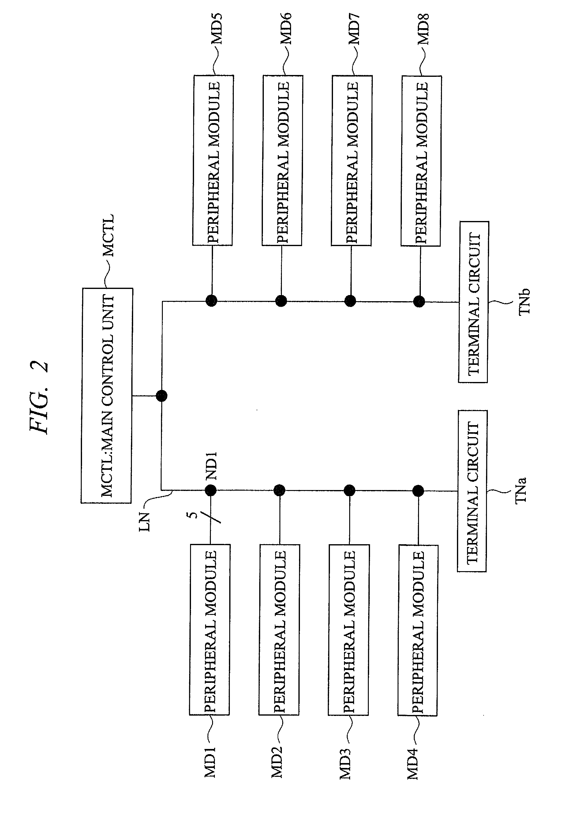
[0075]FIG. 11 is a block diagram showing an example of a configuration of a serial bus system according to the second embodiment of the present invention. As with FIG. 2, the serial bus system shown in FIG. 11 has a configuration in which a main control unit MCTL_W and a plurality of peripheral modules MD_WL to MD_W8 are electrically connected on the communication line LN, and both ends of the communication line LN are provided with the terminal circuits TNa and TNb.

[0076]The difference from FIG. 2 is the wiring topology in which the communication line LN is once extended into the interior of each of the peripheral modules MD_W, and the part extend...

third embodiment

[0088](Third Embodiment)

[0089]In a third embodiment, an example in which an automatic vending machine is composed by applying the wiring topology of FIG. 11 described in the second embodiment will be described. FIG. 14 is a block diagram showing an example of a configuration of the automatic vending machine according to the third embodiment of the present invention.

[0090]The automatic vending machine shown in FIG. 14 has the configuration in which, as with FIG. 11, a main control unit MCTL_W and a plurality of peripheral modules MD_Wa to MD_Wj are electrically connected on the communication line LN, and the terminal circuits TNa and TNb are connected at both ends of the communication line LN. MD_Wa is a wireless modem and has a function of carrying out wireless transmission / reception of data with outside via an antenna ANT. MD_Wb is a money amount display unit and has the function of displaying the money inserted by a user.

[0091]MD_Wc is a so-called coin mechanism and has the functi...


PUM


Abstract

In a configuration where a main control unit and various peripheral modules are bus-connected on a communication line, the communication line includes a control line in addition to signal lines serving as a differential pair. The control line is, for example, a bus of the logical AND. When the main control unit drives the control line to a ‘L’ level for a certain period of time or more, the peripheral modules detect that and carry out a hardware reset for itself. When the main control unit issues a command to output a value of a particular bit of own identification number to the peripheral modules via the signal lines, the peripheral modules output the result to the control line, and the control line performs an AND operation. By utilizing the AND operation result, automatic address allocation to the peripheral modules is carried out.

Description

CROSS-REFERENCE TO RELATED APPLICATION[0001]The present application claims priority from Japanese Patent Application No. JP 2007-178294 filed on Jul. 6, 2007, the content of which is hereby incorporated by reference into this application.TECHNICAL FIELD OF THE INVENTION[0002]The present invention relates to an automatic vending machine and a serial bus system suitable to the same. More particularly, the present invention relates to an input / output interface technique of a serial bus system.BACKGROUND OF THE INVENTION[0003]For example, Japanese Patent Application Laid-Open Publication No. 2001-266231 (Patent Document 1) discloses a configuration in which a unit body is provided with a plurality of general-purpose interfaces based on RS-232C, and each of the general-purpose interfaces is connected to, for example, a DoPa module (trademark), a PHS module, a modem device, or a personal computer in order to collect the data of various settings or sales of an automatic vending machine onl...

Claims


Application Information

Patent Timeline
Patent Type & Authority Patents(United States)
IPC IPC(8): G06F13/00
CPCG07F9/02
Inventor TANAKA, KATSUYOSHIKISHIHARA, ATSUSHI
Owner HITACHI ULSI SYST CO LTD
Why Eureka
Try Eureka