Integrated load sensing system

a load sensing system and integrated technology, applied in the direction of power amplification, instruments, transportation and packaging, etc., can solve the problems of affecting the inspection cycle of currently uninstrumented platforms, the failure of single load path actuators, and the complete loss of control of horizontal stabilizers, so as to achieve the effect of minimal electrical and mechanical interfacing, easy retrofit into existing applications, and improved inspection cycles

Active Publication Date: 2012-06-05
SAFRAN ELECTRONICS & DEFENSE AVIONICS USA LLC
View PDF28 Cites 24 Cited by
  • Summary
  • Abstract
  • Description
  • Claims
  • Application Information

AI Technical Summary

Benefits of technology

[0020]A lower portion of the primary load path is defined by the load from the ball screw to the ball nut assembly to the lower primary gimbal assembly to the control surface. A lower portion of the secondary load path is defined by the load from the ball screw to the secondary inverted thread nut to the yoke assembly to the lower load sensing assembly to the lower secondary gimbal assembly to the control surface. The lower load sensing assembly provides lower indications of the applied forces in the lower portion of the secondary load path when the lower portion of the primary load path is disconnected.
[0022]The present invention provides adjustment / rigging-free, extremely light and compact solution which directly measures secondary load path loading in real time. By virtue of its fully integrated design, it is easily retrofit into existing applications with minimal electrical and mechanical interfacing. System controllers previously blind to path loading could make decisions based on direct measurement rather than depending on assumption. Furthermore, inspection cycles of currently uninstrumented platforms can be improved by retrofitting the present invention. Costs associated with testing the present invention are reduced by requiring no special tools for in situ testing. In addition, the testing in the present invention fully tests all aspect of the system from the bonding of the strain sensing elements to the BCEECA subsystem, logic module, enunciation module, and power supply conversion. It is hermetically sealed and easily field replaceable as well as designed to aerospace environmental requirements per the RTCA DO160 standard.

Problems solved by technology

Failures of the primary load path such as caused by the shearing off of the connecting trunnion segment, ball screw disconnect or by the loss of nut ball members from the ball nut assembly can result in the complete loss of control of the horizontal stabilizer.
However, stabilizer actuators have frequently been provided with a secondary load path for alternate control of the stabilizer and structural integrity, as well as to meet the required level of safety (failure of single load path actuator has a catastrophic outcome on the aircraft).
The transition of control to the secondary load path can occur quite rapidly whereby failure of the primary load path is not necessarily detected by the operator or pilot.
However, in the event of a subsequent failure of the secondary load path through continued, periodic use, control of the stabilizer will be completely lost which could result in erratic, oscillatory movement of the stabilizer whereby the ability of the pilot or operator to control the aircraft could be substantially inhibited.
The jammed and immobilized actuator will stall the drive motor which is detected and annunciated by the system controller, thus annunciating the fault in the actuator.
This solution becomes limited when dealing with large body aircraft.
With large body aircraft the torque needed to stall the drive motor by means of locking and jamming the ball screw is extremely high (more than 10,000 in-lb) and is infeasible and unachievable without hugely impacting the envelope (volume) and weight of the actuator (especially the ball screw gimbal area where the lock is mounted).
However, the '702 device is deficient because it assumes that the surface is directly mounted to the aircraft structure and does not address the need to monitor the integrity of the load paths of actuators that actuate the control surfaces and that are typically mounted between the aircraft structure and the respective control surfaces.

Method used


Image

  • Integrated load sensing system
  • Integrated load sensing system
  • Integrated load sensing system

Examples


Embodiment Construction

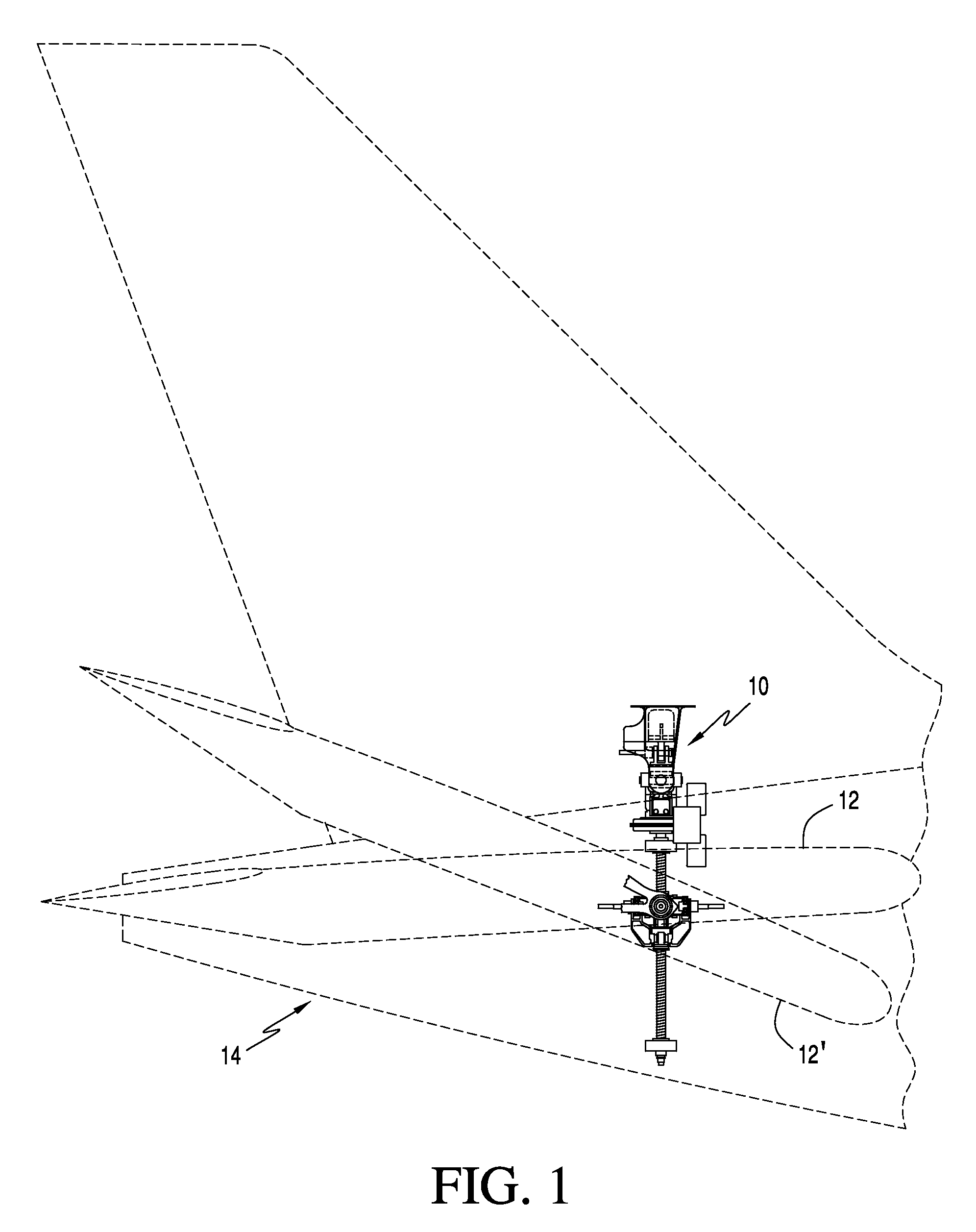
[0034]Referring now to the drawings and the characters of reference marked thereon, FIG. 1 illustrates the actuator system, designated generally as 10, in accordance with the principles of the present invention, embodied for use with a horizontal stabilizer 12 of an aircraft 14. The actuator 10 functions along its stroke to facilitate pivoting of the horizontal stabilizer 12 as shown by numeral designation 12′ (aircraft pitched nose up).

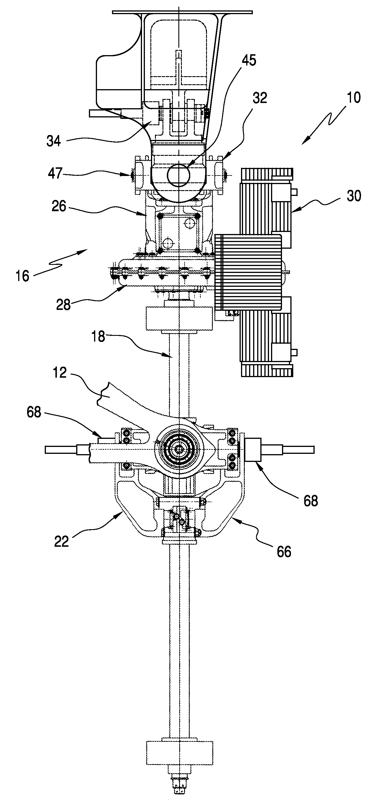
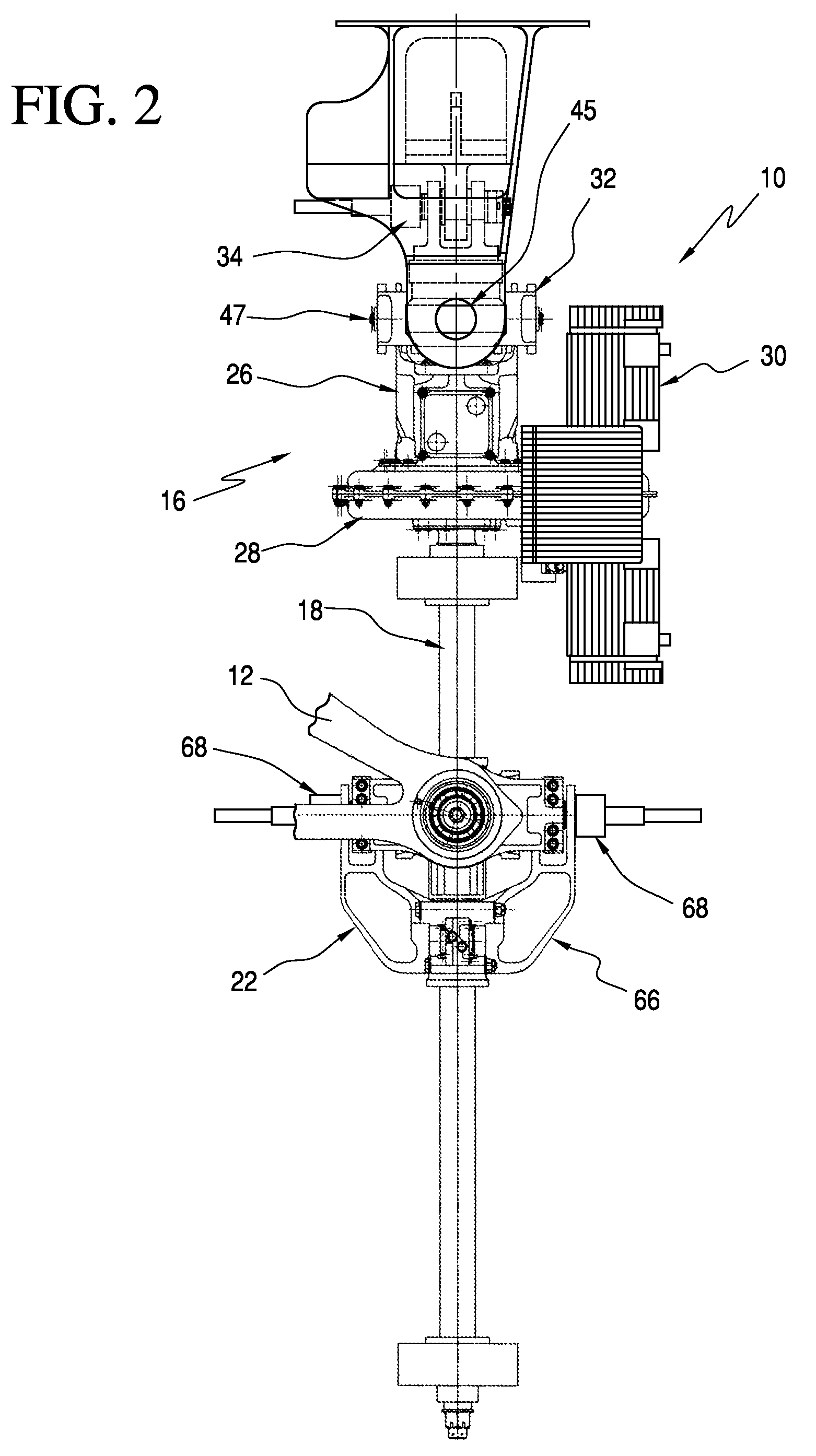
[0035]Referring now to FIG. 2, the actuator system includes an upper actuator assembly 16; a ball screw assembly 18; a tie-rod assembly 20 (shown in subsequent figures); and, a lower actuator assembly 22.

[0036]With references to FIGS. 2-6, the upper actuator assembly 16 includes an upper actuator assembly housing 26; a gear assembly 28 supported by the upper actuator assembly housing 26; a motor assembly 30 operatively associated with the gear assembly 28; an upper primary gimbal assembly 32 mounted to the upper actuator assembly housing 26; and, an ...


PUM


Abstract

An integrated load sensing system includes a housing including a coupling pin portion thereof. A bridge circuit includes a set of strain gauges bonded to the coupling pin portion. A bridge circuit excitation, error correction, and amplification (BCEECA) subsystem is operatively connected to the bridge circuit for receiving indications of shear load from the strain gauges, correcting signal error, and amplifying the indications of shear load. The BCEECA subsystem provides amplified output signals. A power conditioning module is operatively connected to the BCEECA subsystem for receiving power from an external power supply and conditioning power to an appropriate state for driving the bridge circuit as well as an appropriate state for error correction and amplification circuitry within the BCEECA subsystem. A logic module compares the amplified output signals to a predetermined signal threshold and provides latching of enunciation in accordance with a selected delay after the threshold is surpassed. An enunciation element providing enunciation of the output signals surpassing the signal threshold in accordance with the logic module. The bridge circuit, the BCEECA subsystem, the power conditioning module, the logic module, and the enunciation element are contained and sealed within the housing. The invention includes a method for in situ testing of a shear load sensing system for a mechanical system.

Description

BACKGROUND OF THE INVENTION[0001]1. Field of the Invention[0002]The present invention relates to load sensing systems and more particularly to a load sensing system particularly adaptable for use with aircraft actuation systems for providing load path integrity monitoring.[0003]2. Description of the Related Art[0004]Modern aircraft have horizontal stabilizers located at the rear tail section of the fuselage or the forward section that are pivotally supported relative to the airplane fuselage to “trim” the aircraft during flight by selective adjustment by the operator or auto-pilot from an internal control unit. The stabilizer actuator is a variable length structural link connecting the horizontal stabilizer control surface to the fuselage structure and used to control the pitch (attitude) of the aircraft during take off, cruise and landing phases under different aerodynamic loading conditions. The stabilizer actuator is also used to recover the aircraft during severe aircraft stall ...

Claims


Application Information

Patent Timeline
Patent Type & Authority Patents(United States)
IPC IPC(8): B64C13/38
CPCB64C13/24G01L1/2225G01L5/22
Inventor SHAHEEN, MILAD A.WRIGHT, ANDREW M.
Owner SAFRAN ELECTRONICS & DEFENSE AVIONICS USA LLC
Why Eureka
Try Eureka