
Hybrid ion source/multimode ion source

a hybrid ion source and multi-mode technology, applied in the field of ion implantation systems, can solve the problems of low power, ion source design for both areas of operation has proved to be problematic, and adds considerable cost and complexity to the system, and achieves the effect of efficient and timely manner

Active Publication Date: 2012-06-05
AXCELIS TECHNOLOGIES
View PDF9 Cites 8 Cited by
  • Summary
  • Abstract
  • Description
  • Claims
  • Application Information

AI Technical Summary

Benefits of technology

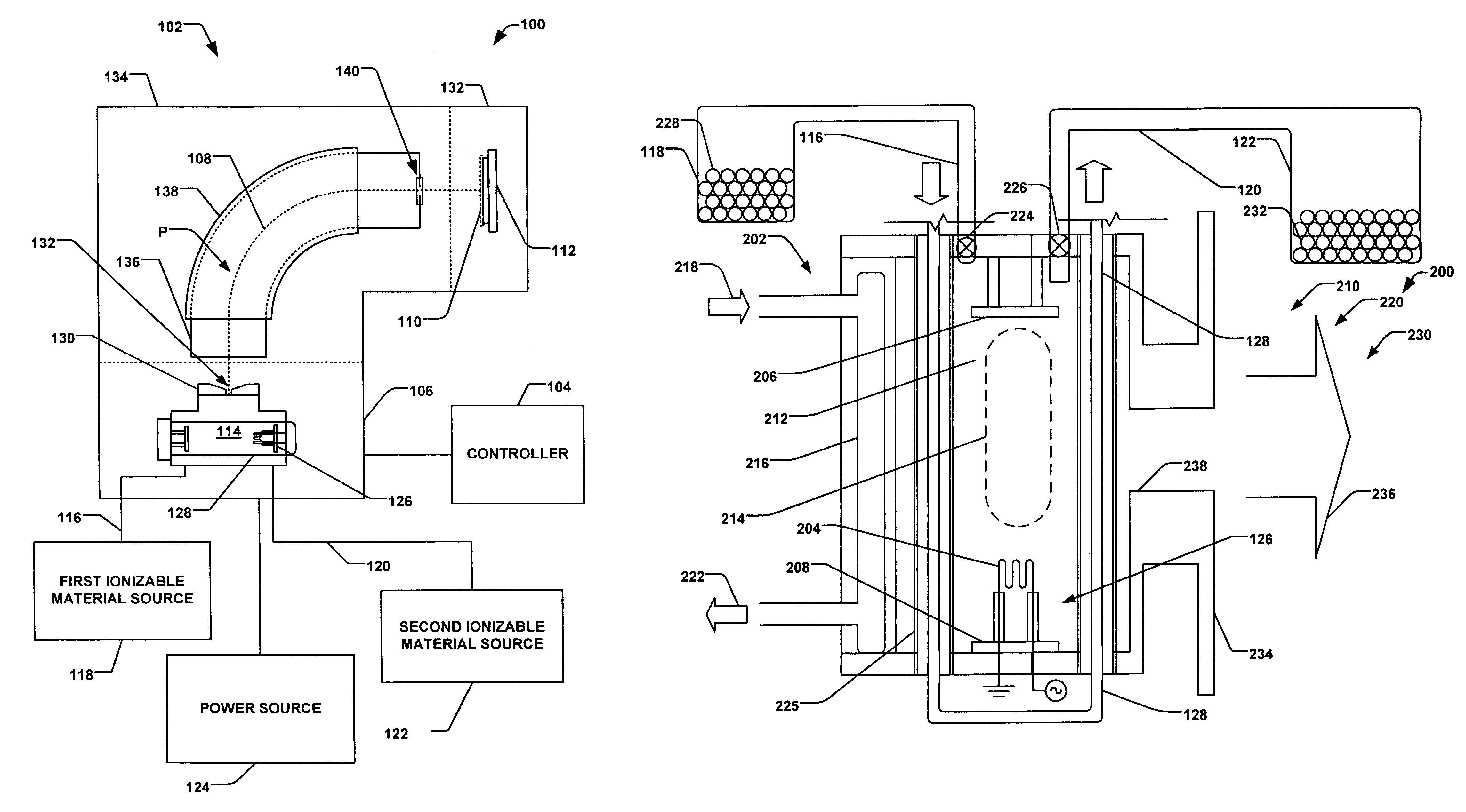
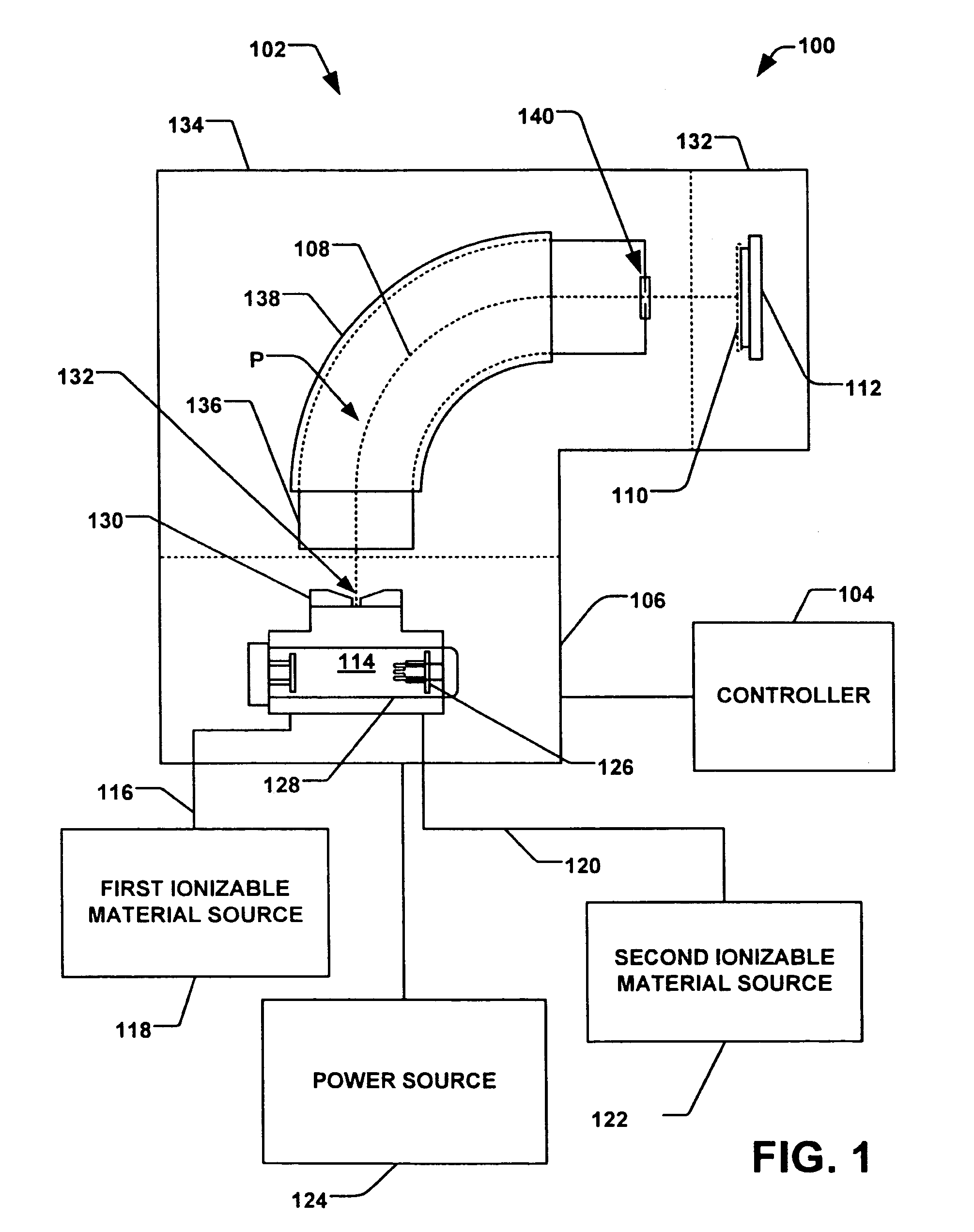
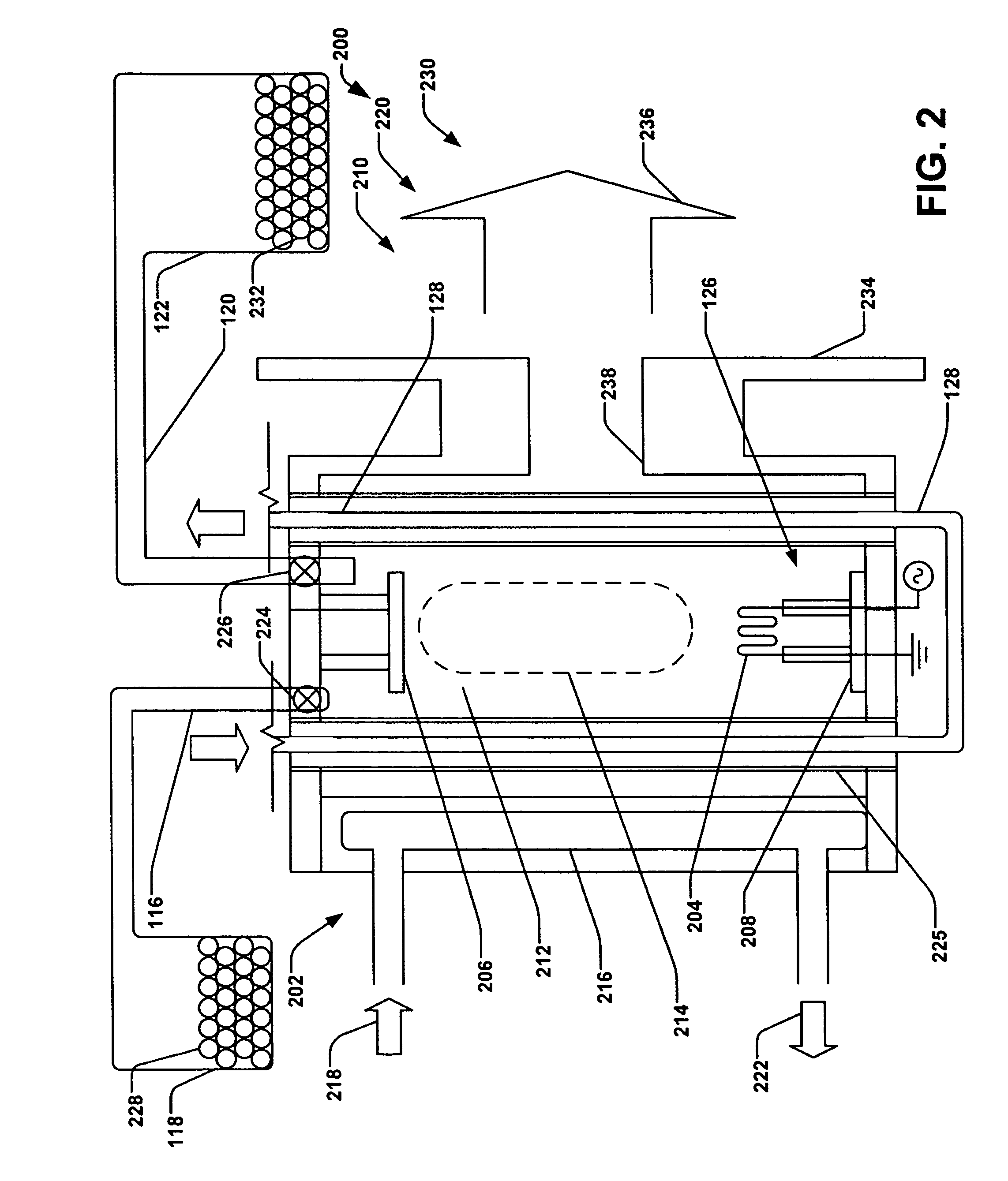
The present invention provides a system, apparatus, and method for efficiently operating an ion source in a low power dc discharge mode, a high power discharge mode, and a high power clean mode. The ion source can be transitioned from one power mode to another power mode and from one ion source material to another ion source material in an efficient and timely manner. The ion source achieves different power modes by employing a hybrid ion source configured selectively with an RF discharge mode or a DC discharge mode or both within the ionization chamber. The ion source can be used in an ion implantation system and can provide in-situ cleaning. The invention allows for the efficient and effective operation of the ion source, improving the efficiency and flexibility of the ion implantation process.

Problems solved by technology

One drawback to using a single mode ion source for implanting various species of ions is that at times it is desirable that the ion source be operated at low density, and therefore low power in order to prevent disassociation of the large molecules utilized within the ion source.
Ion source design for both areas of operation has proven to be problematic.
Present technology typically uses an external fluorine generator, adding considerable cost and complexity to the system.
The external fluorine systems can introduce problems, for example process variability, reduced yields, flow rate issues, and the like.

Method used


Image

  • Hybrid ion source/multimode ion source
  • Hybrid ion source/multimode ion source
  • Hybrid ion source/multimode ion source

Examples


Embodiment Construction

[0018]The present invention is directed generally towards an improved ion source apparatus, ion implantation system and a cleaning process and method for changing ionization species used in ion implantation. More particularly, the apparatus, system, and method provide rapid change of various discharge modes and source gases utilized in the ion implantation system. Accordingly, the present invention will now be described with reference to the drawings, wherein like reference numerals are used to refer to like elements throughout. It should be understood that the description of these aspects are merely illustrative and that they should not be taken in a limiting sense. In the following description, for purposes of explanation, numerous specific details are set forth in order to provide a thorough understanding of the present invention. It will be evident to one skilled in the art, however, that the present invention may be practiced without these specific details.

[0019]Referring now t...


PUM


Abstract

A hybrid ion source, comprising a source body configured to create plasma therein, from a first material, wherein the first material comprises one of monatomic gases, small molecule gases, large molecule gases, reactive gases, and solids, a low power plasma generation component operably associated with the source body, a high power plasma generation component operably associated with the source body and an extraction aperture configured to extract ions of the ion plasma from the source body.

Description

REFERENCE TO RELATED APPLICATION[0001]This application claims priority to and the benefit of U.S. Provisional Application Ser. No. 60 / 952,916 which was filed Jul. 31, 2007, entitled HYBRID ION SOURCE / MULTIMODE ION SOURCE, the entirety of which is hereby incorporated by reference as if fully set forth herein.FIELD OF THE INVENTION[0002]The present invention relates generally to ion implantation systems, and more specifically to a system, apparatus, and method for utilizing multiple modes of operation in a hybrid ion source for ion implantation.BACKGROUND OF THE INVENTION[0003]In the manufacture of semiconductor devices and further products, ion implantation systems are used to impart dopant elements into semiconductor wafers, display panels, glass substrates, and the like. Typical ion implantation systems or ion implanters implant a workpiece with an ion beam of impurities in order to produce n-type and / or p-type doped regions, or to form passivation layers in the workpiece. When use...

Claims


Application Information

Patent Timeline
Patent Type & Authority Patents(United States)
IPC IPC(8): H01J27/00
CPCH01J37/08H01J37/3171H01J2237/30472H01J2237/0827
Inventor DIVERGILIO, WILLIAM F.TIEGER, DANIEL R.GRAF, MICHAEL A.
Owner AXCELIS TECHNOLOGIES
Learn More