MRI apparatus with RF surface coil having at least three resonance frequencies

a surface coil and magnetic resonance imaging technology, applied in the field of magnetic resonance imaging (mri), can solve the problems of difficult to maintain the precision of adjustment, difficult to maintain high detection efficiency with an rf coil, and time and effort, and achieve the effect of high detection efficiency

Inactive Publication Date: 2012-06-05
HITACHI LTD
View PDF20 Cites 19 Cited by
  • Summary
  • Abstract
  • Description
  • Claims
  • Application Information

AI Technical Summary

Benefits of technology

[0014]According to the present invention, magnetic resonance signals can be received always with high detection efficiency by an RF coil of an MRI apparatus, even if significant loss is caused in the RF coil, or test subject is changed.

Problems solved by technology

If capacity of the capacitor is changed to adjust the phase, it takes time and effort, and it is difficult to maintain precision of the adjustment.
For this reason, it is difficult to maintain high detection efficiency with an RF coil.
In particular, when imaging is performed by using an MRI apparatus using a high magnetic field intensity higher than 3 T (tesla) or by using a highly sensitive RF coil, coupling of a test subject and an RF coil becomes strong, and therefore significant loss is caused in the RF coil.
Therefore, a large degree of change of capacity of the capacitor is needed for the retune.
A capacitor having a capacity of 1 pF or less scarcely allows adjustable range, and shows low durability.
Therefore, with such a capacitor, it is difficult to restore magnetic resonance signal detection efficiency by readjusting the RF coil via change of capacity of the capacitor.
Further, since degree of the loss caused in an RF coil greatly depends on test subject, difficult adjustment is needed for every test subject in order to maintain detection efficiency.

Method used


Image

  • MRI apparatus with RF surface coil having at least three resonance frequencies
  • MRI apparatus with RF surface coil having at least three resonance frequencies
  • MRI apparatus with RF surface coil having at least three resonance frequencies

Examples


first embodiment

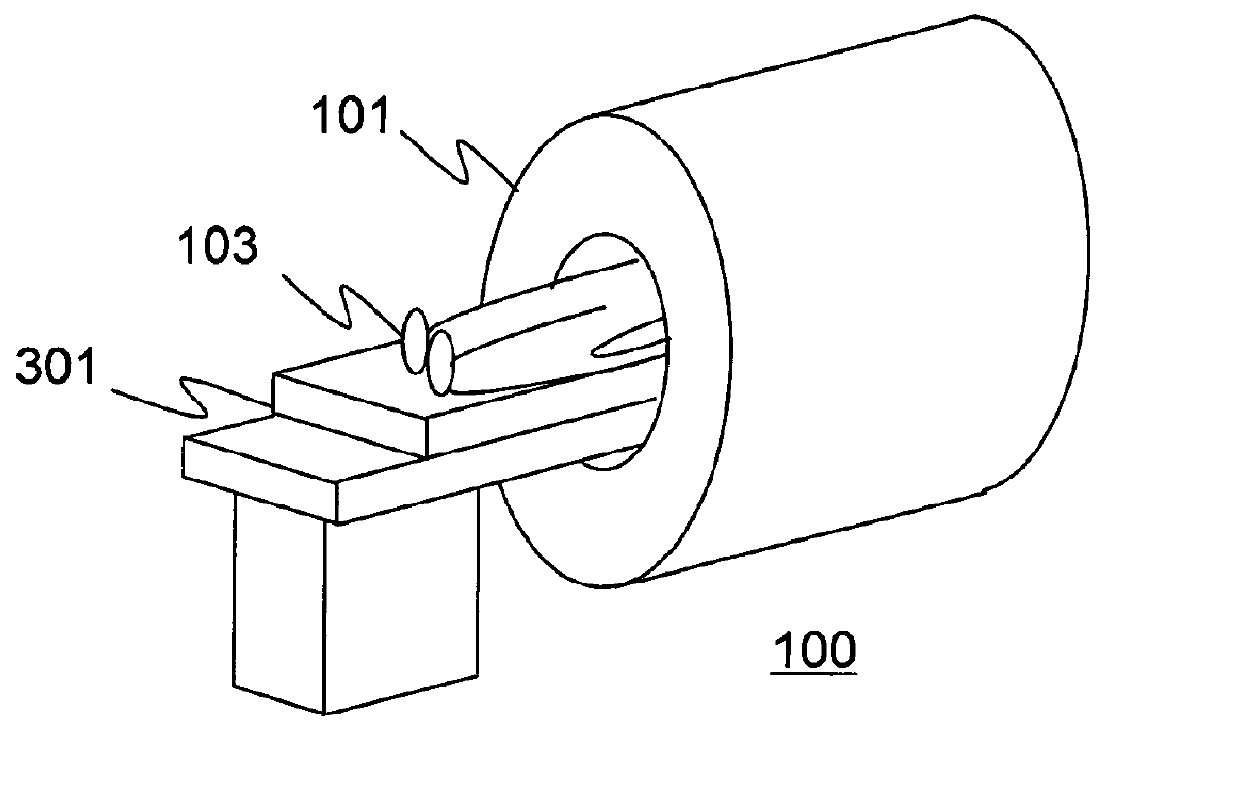
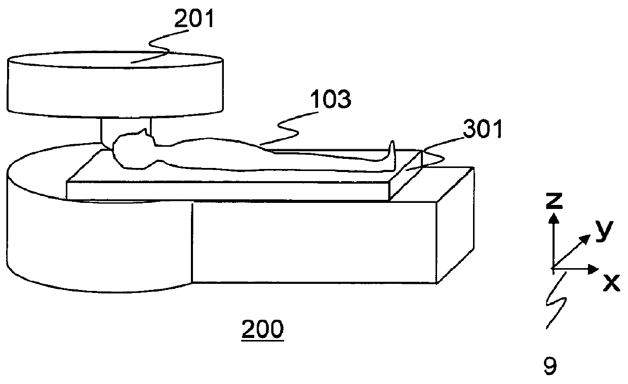
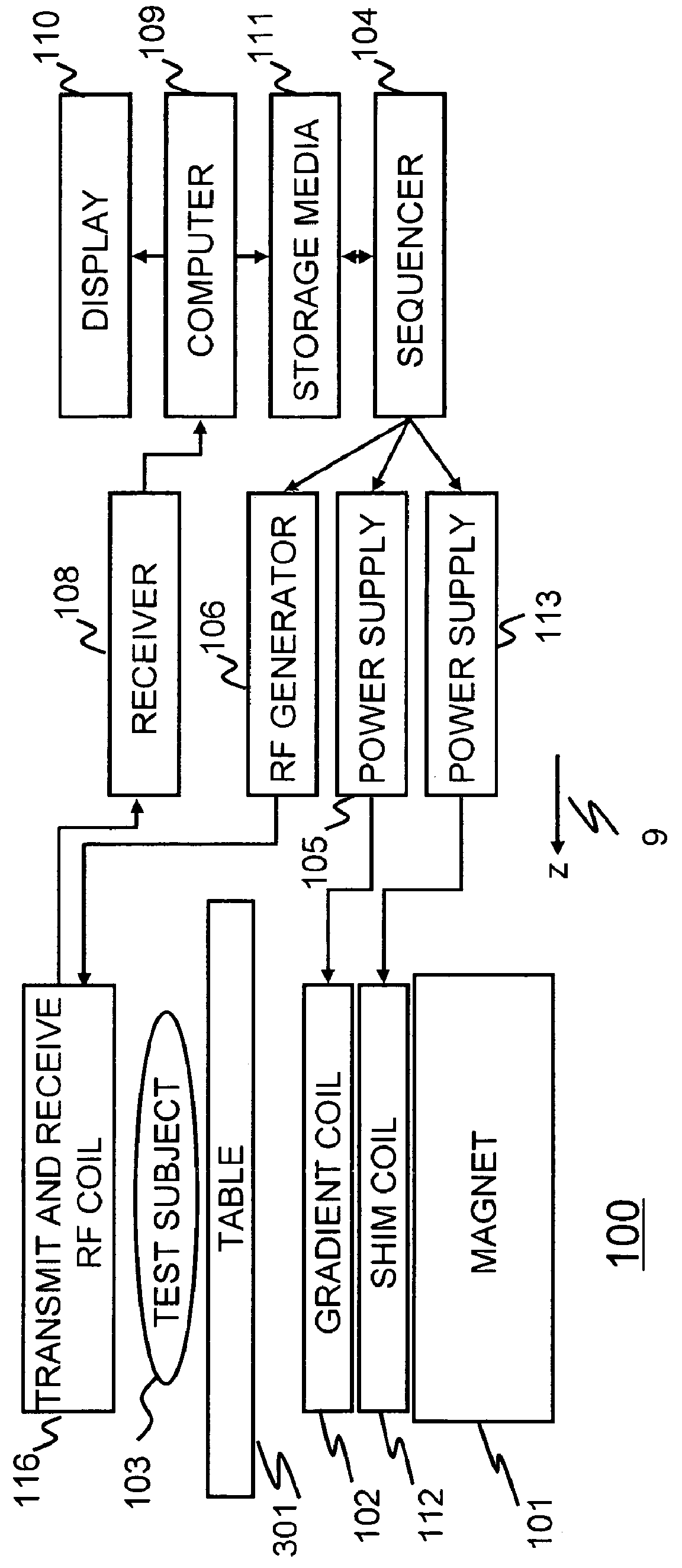
[0037]The first embodiment of the present invention will be explained below. Total configuration of an MRI apparatus of this embodiment is explained first. FIG. 1A and FIG. 1B include schematic views of MRI apparatuses of this embodiment. In the diagram, the direction of the z-axis of the coordinate 9 is the direction of static magnetic field. An MRI apparatus 100 shown in FIG. 1A is provided with a horizontal magnetic field type magnet 101. An MRI apparatus 200 shown in FIG. 1B is provided with a vertical magnetic field type magnet 201. These MRI apparatuses 100 and 200 are provided with a table 301 on which a test subject 103 is placed. This embodiment can be applied to both the MRI apparatus 100 provided with the horizontal magnetic field type magnet 101, and the MRI apparatus 200 provided with the vertical magnetic field type magnet 201. This embodiment will be explained below by referring to the MRI apparatus 100 having the horizontal magnetic field type magnet 101 as an exampl...

second embodiment

[0107]Hereafter, the second embodiment of the present invention will be explained. The MRI apparatus according to this embodiment is fundamentally the same as that of the first embodiment. However, in this embodiment, coils made of combination of two surface coils 570, which are modifications of the first embodiment, are used as the transmit and receive RF coil 116 for realizing quadrature detection (QD), which improves irradiation efficiency and reception sensitivity of the transmit and receive RF coil. Hereafter, configurations different from those of the first embodiment will be mainly explained.

[0108]FIG. 12A and FIG. 12B are diagrams for explaining a transmit and receive RF coil 590 of this embodiment. And FIG. 12A shows a schematic view of the transmit and receive RF coil 590. In the diagram, the z-axis direction of the coordinate 9 is the direction of the static magnetic field. As shown in this diagram, the transmit and receive RF coil 590 of this embodiment is provided with ...

third embodiment

[0117]The third embodiment of the present invention will be explained below. The MRI apparatus according to this embodiment is fundamentally the same as that of the first embodiment. However, in this embodiment, a transmit RF coil and a receive RF coil are independently provided instead of the transmit and receive RF coil 116 of the first embodiment. Here, explanation will be made by referring to a case where a birdcage type RF coil having a birdcage shape is used as the transmit RF coil and a loop coil having a surface coil shape is used for the receive RF coil as an example. Hereafter, configurations different from those of the first embodiment will be mainly explained.

[0118]FIG. 14 shows a block diagram for explaining connection of an RF coil 600 of this embodiment to an RF generator 106 and a receiver 108. As shown in this diagram, the RF coil 600 of this embodiment is provided with a birdcage type RF coil 601 which is a transmit RF coil, and a surface coil 603 which is a receiv...


PUM


Abstract

An RF coil having at least three different resonance frequencies, wherein one of the resonance frequencies is adjusted to be a frequency fA of a magnetic resonance signal generated by a test subject, and the coil is adjusted so that ratio of difference between the frequency fA and a first frequency fB lower than fA and nearest to fA among the resonance frequencies (fA−fB), and difference between the frequency fA and a second resonance frequency fC higher than fA and nearest to the frequency fA among the resonance frequencies (fC−fA), should be from 0.5 to 2.0. There is provided a technique for receiving magnetic resonance signals always with high detection efficiency by an RF coil of an MRI apparatus even if significant loss is caused in the RF coil, or test subject is changed.

Description

CLAIM OF PRIORITY[0001]The present application claims priority from Japanese Patent Application No. 2007-299622 filed on Nov. 19, 2007, the content of which is hereby incorporated by reference into this application.BACKGROUND OF THE INVENTION[0002]The present invention relates to a magnetic resonance imaging (MRI) apparatus, in particular, an RF (radio frequency) coil for obtaining magnetic resonance signals.[0003]MRI apparatus is medical diagnostic imaging apparatus which induce magnetic resonance in nuclei in an arbitrary cross-section passing horizontally through a test subject, and obtaining a tomogram in the section from generated magnetic resonance signals. In general, an RF magnetic field is irradiated by an RF coil to excite hydrogen nuclei (1H), and generated magnetic resonance (RF magnetic field) signals are detected.[0004]An RF coil irradiates an RF magnetic field, and receive magnetic resonance signals. This coil was constructed with parallel resonance circuit or series ...

Claims


Application Information

Patent Timeline
Patent Type & Authority Patents(United States)
IPC IPC(8): G01V3/00
CPCG01R33/34046G01R33/34053G01R33/34069G01R33/341G01R33/3415G01R33/3635
Inventor OTAKE, YOSUKESOUTOME, YOSHIHISAHIRATA, KOJIBITO, YOSHITAKA
Owner HITACHI LTD
Why Eureka
Try Eureka