Method and apparatus for controlling cooling temperature and pressure in wood veneer jet dryers

a technology of wood veneer and jet dryer, which is applied in the direction of drying solid materials, drying machines, drying machines with progressive movements, etc., can solve the problem of slow temperature set point of air supply fans

Active Publication Date: 2012-06-12
USNRKOCKUMS CANCAR
View PDF12 Cites 24 Cited by
  • Summary
  • Abstract
  • Description
  • Claims
  • Application Information

AI Technical Summary

Benefits of technology

[0007]Thus, in one aspect of the present invention, the first cooling section, which is attached directly to the last heated dryer section, is modified to create a “pressure seal” for minimizing both the flow of heated process air from the dryer into the cooling zone or the flow of cool air from the cooling zone into the enclosed heated dryer. In one embodiment the first cooling section is fitted, in its discharge vent, with a tube-axial extractor fan and motor controlled by a frequency drive, conjoined with a modulating, balanced-blade damper. The section is mechanically sealed from both the enclosed dryer and second cooling section by two sets of baffle-like “stop-offs” that are mounted between the dryer rolls at the beginning and end of the section, restricting the movement of air in and out of the first cooling section. The stop-offs extend laterally across the veneer flow path and work in conjunction with the veneer conveying rolls. They, therefore, only allow restricted leakage or entrance of air past the pressure seal section entrance and exit.
[0008]Pressure-sensing manifolds are mounted on either side of the stop-offs between the enclosed dryer and first cooling section and are piped to a pressure transducer, which continuously monitors the differential pressure between the heated dryer and first cooling section. The signal from the transducer is processed in the dryer programmable logic controller (PLC) using a PID loop, described below, with split range control and a “near zero” set point, which produces a signal that both modulates the damper through the first half of the control range and controls the speed of the tube-axial extractor fan through the second half of the control range. The effect of this control is to maintain a slightly higher pressure in the first cooling section with a “near zero” pressure differential between the enclosed dryer and first cooling section, that is the “pressure seal” section, under all operating conditions. The resulting controlled condition minimizes pitch buildup in the dryer and cooler, minimizes volatile organic carbon (VOC) in the cooler vent and improves the drying process thermal efficiency.

Problems solved by technology

If reduced cooling is required the air supply fans slow to satisfy the temperature set point.

Method used


Image

  • Method and apparatus for controlling cooling temperature and pressure in wood veneer jet dryers
  • Method and apparatus for controlling cooling temperature and pressure in wood veneer jet dryers
  • Method and apparatus for controlling cooling temperature and pressure in wood veneer jet dryers

Examples


Embodiment Construction

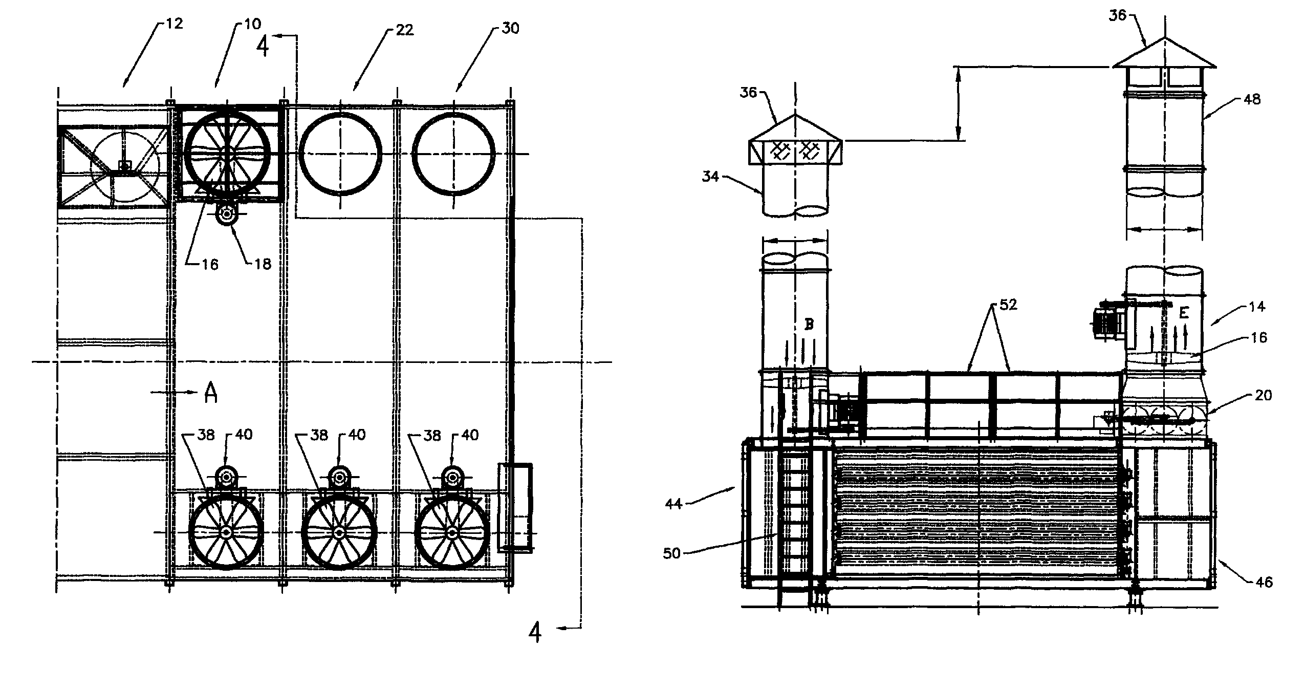
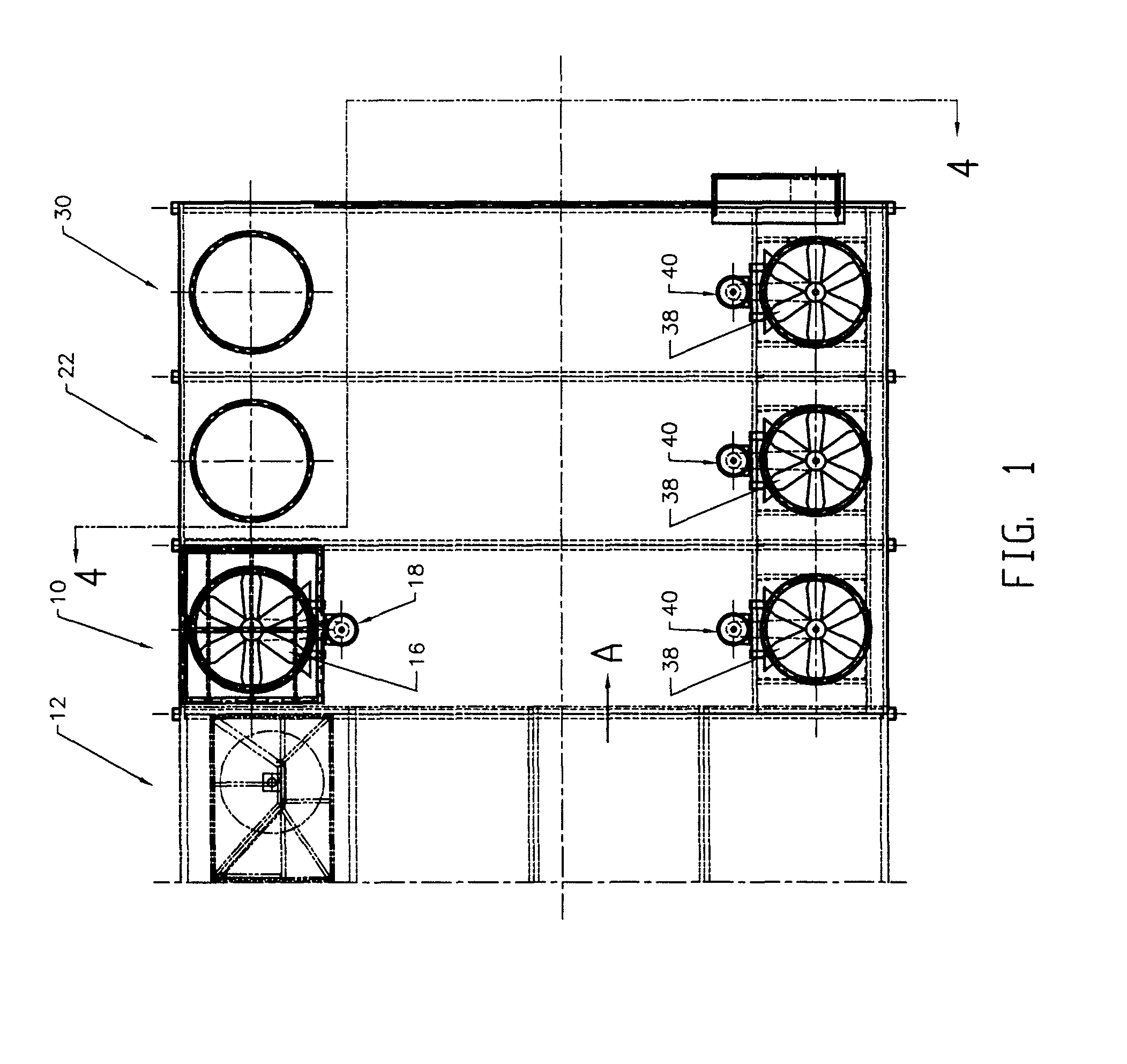
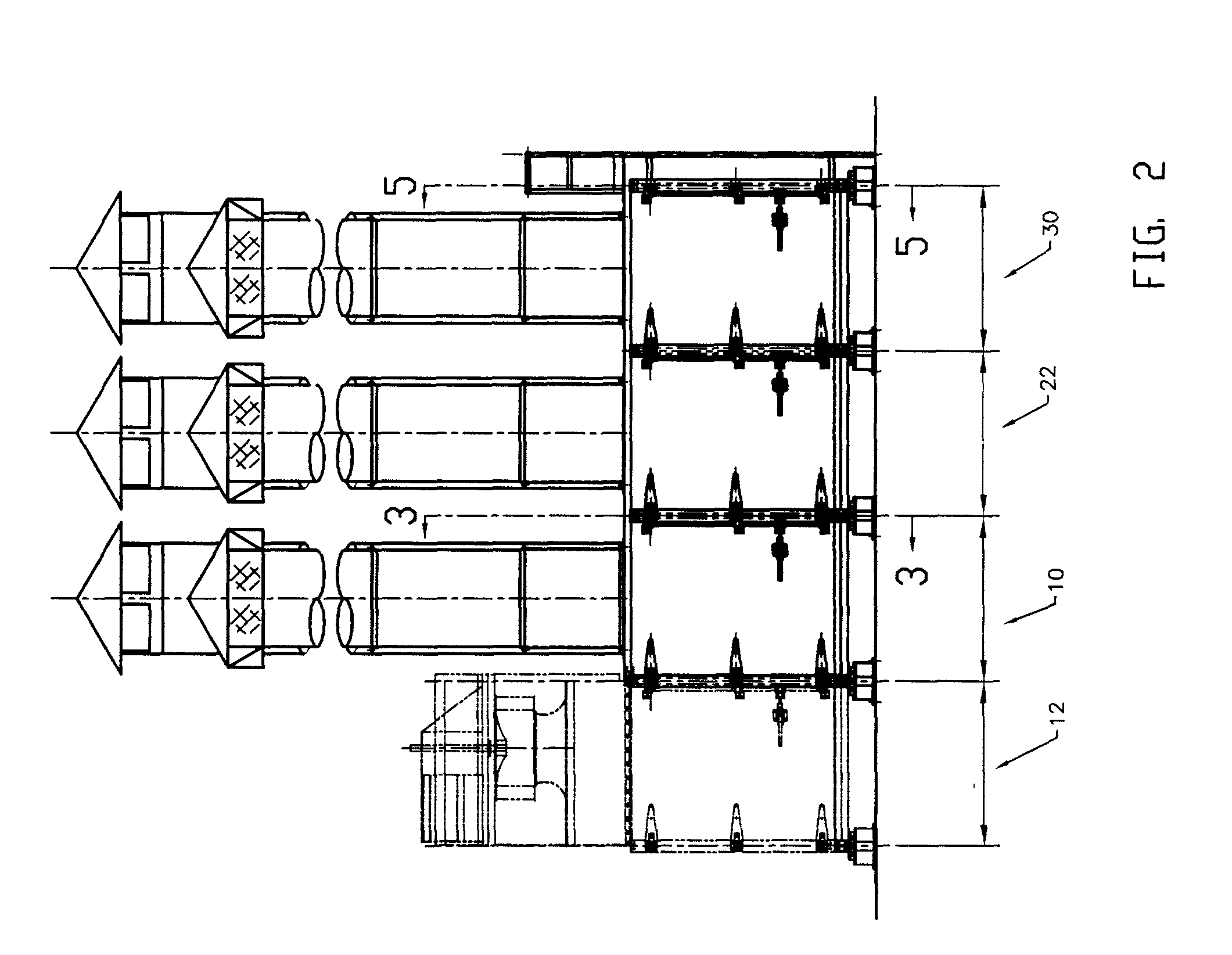
[0026]First cooling section 10 is mounted directly to the last, that is most downstream, heated dryer section 12. Section 10 is modified to create a pressure seal for minimizing both the flow in direction A of heated process air from the dryer air into the cooling zone commencing in section 10 or the flow in the opposite direction of cool air from the cooling zone into the enclosed heated dryer. In one embodiment first cooling section 10 is fitted, in its discharge vent 14, with a tube-axial exhaust fan 16 and motor 18 controlled by a frequency drive, conjoined with a modulating, balanced-blade damper 20. Section 10 is mechanically sealed from both the last dryer section 12 and a downstream second cooling section 22 by two sets of stop-offs 24 that are mounted between the dryer rolls 26 in both the upstream and downstream ends of section 10, thereby restricting the movement of air into and out of first cooling section 10.

[0027]Pressure-sensing manifolds (not shown) are mounted on ei...


PUM

PropertyMeasurementUnit
pressureaaaaaaaaaa
movementaaaaaaaaaa
Temperatureaaaaaaaaaa

Abstract

An apparatus for drying wood veneer includes an elongate drying chamber including a conveyor for conveying material to be dried from an input end to an output end; and a cooling section for cooling veneer leaving the output end of the drying chamber, the cooling section including a pressure controller for maintaining a pressure in the cooling section that is slightly higher than pressure in the drying chamber while maintaining a near-zero pressure differential between the drying chamber and the cooling section.

Description

CROSS REFERENCE TO RELATED APPLICATIONS[0001]This application claims priority from U.S. Provisional Patent Application No. 60 / 900,356 filed Feb. 9, 2007 entitled Method and Apparatus for Controlling Cooling Temperature and Pressure in Wood Veneer Jet Dryers.FIELD OF THE INVENTION[0002]This invention relates to the field of producing wood veneer and in particular to a method and apparatus for controlling the temperature and pressure in the cooling sections of wood veneer jet dryers.BACKGROUND OF THE INVENTION[0003]Applicant is aware of U.S. Pat. No. 5,603,168 which issued to McMahon, Jr. on Feb. 18, 1997 for a Method and Apparatus for Controlling a Dryer wherein it is taught that the cooling section cools into the material exiting the drying chamber of the dryer by blowing ambient air around the material as it travels through the cooling section. A control is provided for maintaining the pressure within the cooling section at a level greater than the pressure in the drying chamber. B...

Claims


Application Information

Patent Timeline
Patent Type & Authority Patents(United States)
IPC IPC(8): F26B3/02
CPCF26B21/10Y10T156/1041F26B2210/14F26B3/32
Inventor MCMAHON, IRVEN J.WOLOWIECKI, BRYAN
Owner USNRKOCKUMS CANCAR
Why Eureka
Try Eureka