Ink for producing catalyst layers
a catalyst layer and ink technology, applied in the direction of metal/metal-oxide/metal-hydroxide catalysts, organic compounds/hydrides/coordination complexes catalysts, fuel cells, etc., can solve the problems of various degradation products in the ink, deterioration of the performance of the catalyst layer or the membrane-electrode assembly, and inability to oxidatively degrad
- Summary
- Abstract
- Description
- Claims
- Application Information
AI Technical Summary
Benefits of technology
Problems solved by technology
Method used
Image
Examples
example 1
[0057]The following components were weighed out and homogenized by means of a dispersion apparatus:
[0058]
0.75 gof supported Pt catalyst (50% Pt / C, from Umicore, Hanau)3.25 gof Nafion ® solution (11.3% in water, from DuPont, USA)9.00 gof water (deionized)12.00 g of 4-hydroxy-4-methyl-2-pentanone (from Merck-Schuchardt,Hohenbrunn / Munich)25.00 g
[0059]The weight ratio of catalyst / Nafion® in this ink is about 2:1. The ink was applied by spraying to the anode side and cathode side of a Nafion® NR 111 ionomer membrane (from DuPont, USA) in the form of a square having an edge length of 7.07 cm (active cell area: 50 cm2) and subsequently dried at 90° C. The adhesion of the catalyst layers to the ionomer membrane was found to be very good. Post-treatment of the catalyst-coated membrane (CCM) to remove any decomposition products did not have to be carried out. After drying, the CCM was placed between two gas diffusion layers (TGPH-060, from Toray, Japan) and measured in a PEM full cell in hyd...
example 2
[0060]The following components were weighed out and homogenized by means of a dispersion apparatus:
[0061]
3.00gof supported Pt catalyst (50% Pt / C, from Umicore, Hanau)13.275gof Nafion ® solution (11.3% in water, from DuPont, USA)6.70gof water (deionized)17.25gof tert-butanol (from Merck, Darmstadt)40.225g
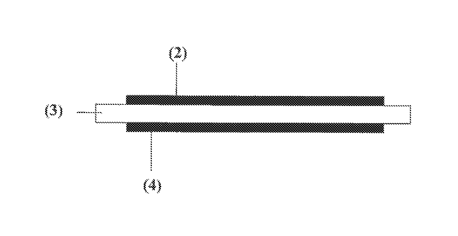
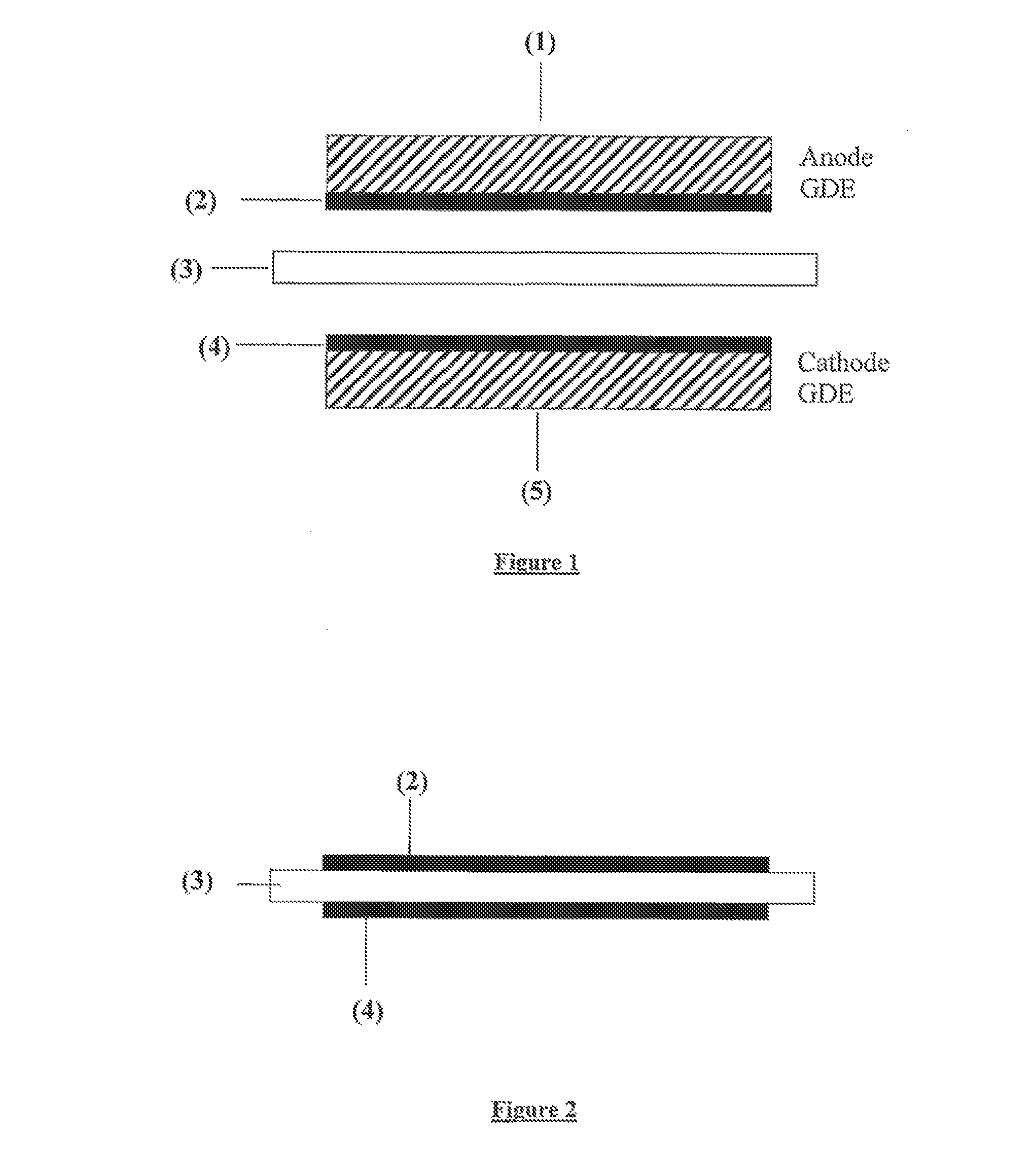
[0062]The ink was applied by screen printing to two gas diffusion layers (type Sigracet 21BC; from SGL, Meitingen, Del.) in the form of a square having an edge length of 7.07 cm (active cell area: 50 cm2) and subsequently dried. Irrigation of the electrodes to remove residues was dispensed with. An ionomer membrane (thickness: 50 microns) was placed between the two electrodes and the combination was subsequently pressed to form a fife-layer membrane-electrode assembly (MEA). The total Pt loading was 0.54 mg of Pt / cm2. The MEA produced in this way was measured in the PEM full cell test. At a current density of 500 mA / cm2, a cell voltage of 700 mV was obtained (power density: 0.35 W / cm...
example 3
[0063]The following components were weighed out and homogenized:
[0064]
0.50 gof supported Pt catalyst (50% Pt / C, from Umicore, Hanau)2.20 gof Nafion ® solution (11.3% in water, from DuPont, USA)2.20 gof water (deionized)19.60 g of 2,5-hexanedione (from Merck-Schuchardt,Hohenbrunn / Munich)24.50 g
[0065]The ink was applied by spraying to the anode side and cathode side of a Nafion® NR 111 ionomer membrane (from DuPont, USA) in the form of a square having an edge length of 7.07 cm (active cell area: 50 cm2) and subsequently dried at 90° C. The adhesion of the catalyst layers to the ionomer membrane was found to be very good. After-treatment of the catalyst-coated membrane (CCM) to remove any decomposition products did not have to be carried out. After drying, the CCM was placed between two gas diffusion layers (TGPH-060, from Toray, Japan) and measured in a PEM full cell in hydrogen / air operation. Very good results were achieved. The total Pt loading was 0.44 mg of Pt / cm2.
PUM
| Property | Measurement | Unit |
|---|---|---|
| temperatures | aaaaa | aaaaa |
| thickness | aaaaa | aaaaa |
| thickness | aaaaa | aaaaa |
Abstract
Description
Claims
Application Information
 - R&D
- Intellectual Property
- Life Sciences
- Materials
- Tech Scout
- Unparalleled Data Quality
- Higher Quality Content
- 60% Fewer Hallucinations
Browse by: Latest US Patents, China's latest patents, Technical Efficacy Thesaurus, Application Domain, Technology Topic, Popular Technical Reports.
© 2025 PatSnap. All rights reserved.Legal|Privacy policy|Modern Slavery Act Transparency Statement|Sitemap|About US| Contact US: help@patsnap.com


