Rapid visual fiber optic cable tester

a fiber optic cable and tester technology, applied in the field of fiber optic cable testers, can solve the problems of high cost of optical fiber cable field testing equipment, equipment that requires periodic factory calibration, and time-consuming in high-volume applications

Inactive Publication Date: 2012-06-26
GUNAL ERKAN
View PDF29 Cites 11 Cited by
  • Summary
  • Abstract
  • Description
  • Claims
  • Application Information

AI Technical Summary

Benefits of technology

[0044]These and other advantages of one or more aspects will become apparent from a consideration of the ensuing description and accompanying drawings of the present application.

Problems solved by technology

OTDR is the most expensive field testing equipment for optical fiber cables.
Furthermore, the equipment requires periodic factory calibration to keep up with industrial test standards.
Another disadvantage is that OTDR only tests one strand at a time, which is very time consuming in high volume applications.
If the jumper cables are dirty, the reference value will be higher and the attenuation measurement will not be accurate.
If the testers have been sitting in a hot van in the summer, or overnight in the winter, this may take an hour or more.
As batteries get weaker, the voltage may drop, and some testers will begin to give erratic results before the testers stop operating completely.
If the testers use disposable batteries, it is unlikely anyone will keep the track of when the batteries were replaced.
If a mandrel does not exist during the time of testing, the consistency of the test results will be suspicious.
Another disadvantage is that end-to-end loss measurement requires testing one or two strands at a time, which is very time consuming in high volume applications.
The technicians often use wireless devices (e.g. mobile phones, radios) to communicate during a troubleshooting operation which can cause interference with the field test instruments during testing and report inaccurate test results.
However, cleanliness is the biggest concern and mostly overlooked factor during troubleshooting.
Every optical fiber testing practice dwells on cleanliness for good reason—poor cleanliness practices are the single greatest cause of problems in optical fiber testing and operation.
There is dust in the air all the time, and the cleaning process itself may create a slight electrostatic charge on the connector that can attract dust out of the air.
If a technician receives a failing test result for one link, the fiber optic connector should not be plugged into another adapter for comparison without cleaning it first—contamination can easily be spread from one adapter port to another.
Unlike traditional optical fiber cabinets that allow a technician to unplug a connector on the inside for cleaning, pre-terminated cassettes are generally factory sealed, making ports difficult to clean if contaminated.
This is also true of the MPO ribbon connectors on the back of the cassettes—they are difficult to clean once they are contaminated.
Some suppliers now offer an advancing-tape cleaner that can be inserted into an adapter or female connector, but they are not always completely successful.
The dust can easily cause attenuation (optical loss) during operation.
The other disadvantage with Serwatka's apparatus is that when the mechanical wheel is aligned with the light source, only two connector endings can be tested at a time.
Therefore, having multiple connector adapters does not speed up the test if the cables being tested have the same type all over.
Therefore, Serwatka's approach is not an ideal solution for rapid field testing in high volume of test conditions.
Thus, because of the fragile nature of fiber optic strands, someone with no technical experience can easily break the fiber optic strand while using Serwatka's apparatus by exceeding the maximum allowed bend radius.
Therefore, his invention is also affected by the cleanliness concerns described above and potential fiber damage while plugging and unplugging the fiber optic connectors during the test.
If the ferrule is cracked or damaged, the entire ferrule will glow red during this test.
However, laser light sources can cause eye damage.
The other problem with the VFL and VFF that they offer only testing on one connector or port at a time, which is time consuming.
However, because of creating a macrobend into the optical fiber strand being tested, this device can break the fiber easily if accidentally used on fragile hot spots.
The test technician could never know which sections of the fiber cable might have fragile spots.
Moreover, this tester is considerably costly to buy and operate.
Therefore, dust is easily carried from one connector to another during inspection.
Furthermore, labor cost becomes high since only one strand or port can be inspected at a time.

Method used


Image

  • Rapid visual fiber optic cable tester
  • Rapid visual fiber optic cable tester
  • Rapid visual fiber optic cable tester

Examples


Embodiment Construction

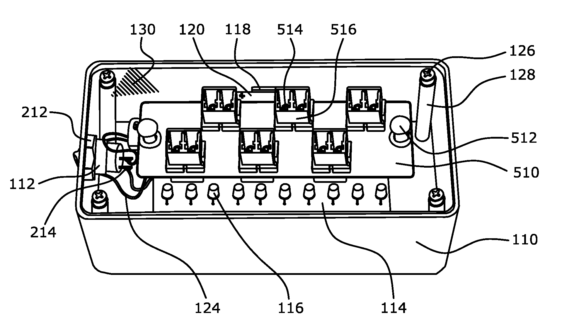
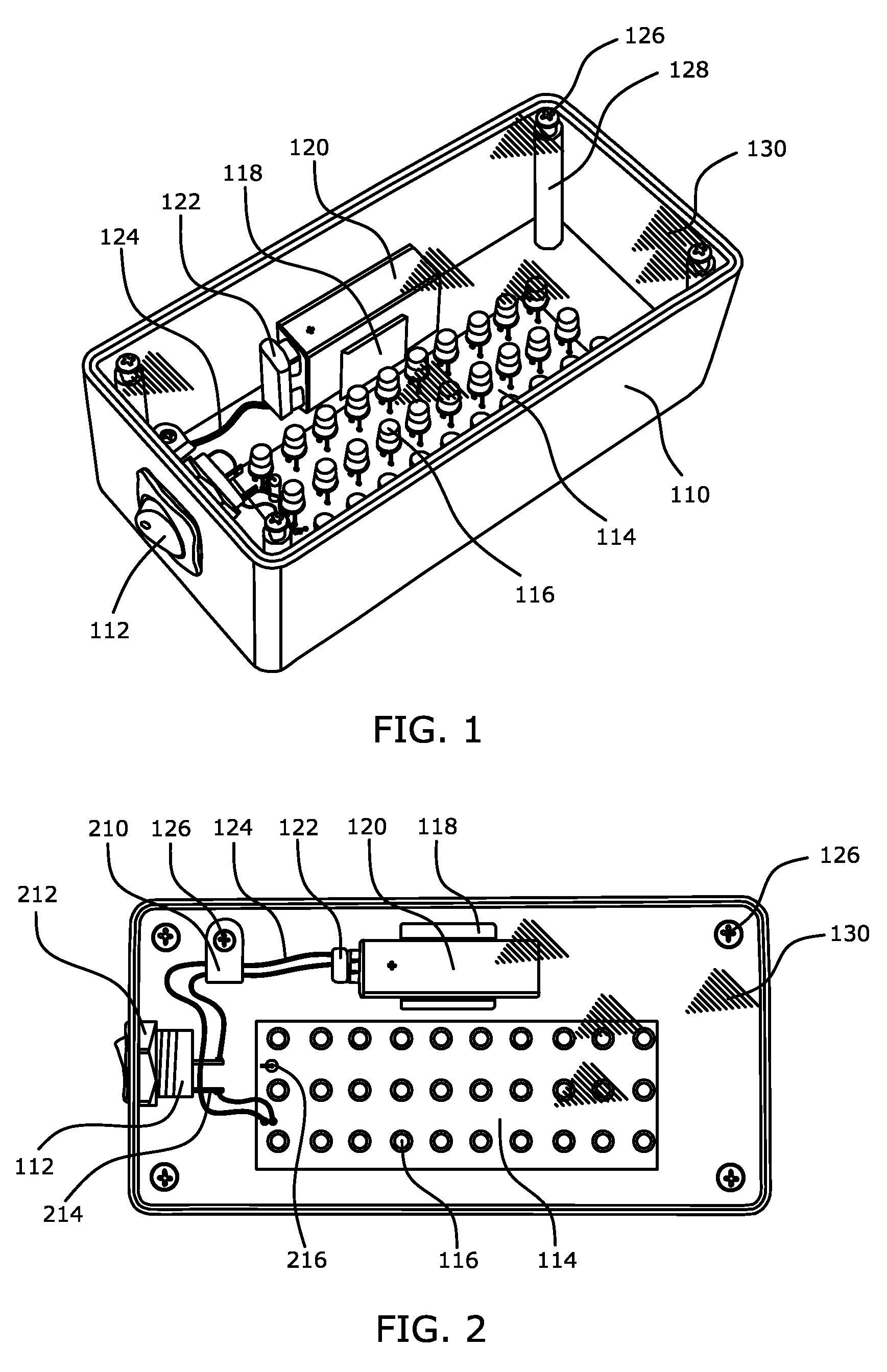
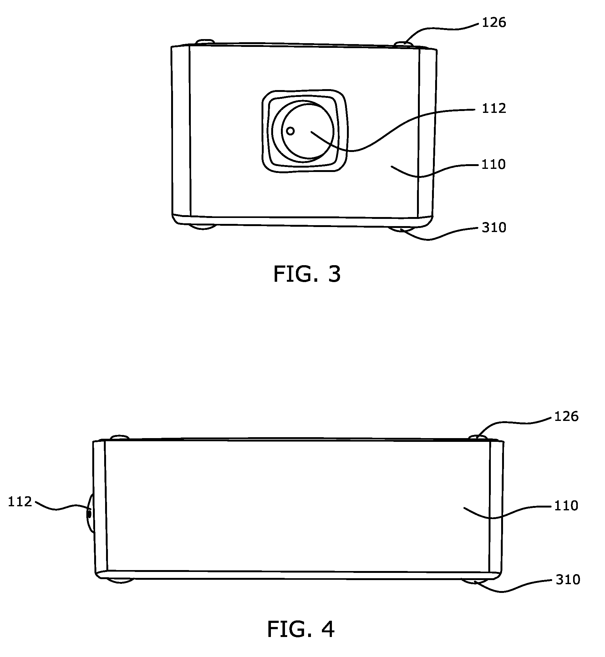
[0053]FIG. 1 shows a perspective view of the rapid visual fiber optic cable tester. Enclosure 110 holds all the components together. Power button 112 is positioned on the side wall of enclosure 110. Circuit board 114 is fixed inside enclosure 110. Each LED 116 (Light Emitting Diode) is mounted in a straight position on the circuit board 114. LEDs 116 are distributed uniformly on the circuit board 114 to provide a uniform visual light pattern through the surface of a transparent screen 130. A total of thirty high intensity LEDs are used to create a basic uniform visual light source in a visible spectrum wavelength range. However, in lieu of LEDs, other light sources can be used as well, such as fluorescent, neon tube, bulb, laser diode, etc. Therefore, there is no limitation for what type and color of light source is used, as long as it is visually sensible.

[0054]Transparent screen 130 in FIG. 1 is located above enclosure 110 and fastened from all corners with screws 126 on support c...


PUM

PropertyMeasurementUnit
optical continuityaaaaaaaaaa
wavelength rangeaaaaaaaaaa
electrical poweraaaaaaaaaa

Abstract

A rapid visual fiber optic cable tester for visually inspecting optical continuity and attenuation of multiple strand fiber optic cable connectors through an existing fiber optic adapter panel, comprising: an enclosure having a uniform visual light source in a visible spectrum wavelength range to provide a uniform visual light pattern on a transparent screen; an electrical power source for powering the uniform visual light source; a power button for controlling the electrical power source; whereby the rapid visual fiber optic cable tester is positioned toward the existing fiber optic adapter panel at one end of the multiple strand fiber optic cable without a direct contact with the connectors; while observing visually at the other end of the cable through existing fiber optic adapter panel for any difference in light intensity between each fiber optic strand; therefore visually detecting optical continuity and attenuation by light intensity levels instantly and rapidly.

Description

BACKGROUND[0001]1. Field[0002]This application relates to fiber optic cable testers in general, and more particularly visual continuity, attenuation and optical loss testers that are used to troubleshoot and inspect fiber optic cable installations.[0003]2. Prior Art[0004]Previously, there have been many solutions and techniques introduced to test optical fiber cables. Commonly used methods can be categorized as follows:[0005](a) OTDR (Optical Time Domain Reflectometer)[0006]An OTDR is used to characterize optical power reflected along optical fibers with a graphical signature on a display screen. The OTDR has the capability to measure the length of the optical fiber and characterize the optical power loss between any two points along the optical fiber. This equipment is built with highly sophisticated and sensitive electronic components. The OTDR, which only requires access to one end of the optical fiber, sends pulses of light into an optical fiber and measures the strength of the ...

Claims


Application Information

Patent Timeline
Patent Type & Authority Patents(United States)
IPC IPC(8): G01N21/00
CPCG01M11/088G01M11/33
Inventor GUNAL, ERKAN
Owner GUNAL ERKAN
Why Eureka
Try Eureka