
System and method for improved real-time cine imaging

a real-time cine imaging and system technology, applied in image enhancement, image analysis, instruments, etc., can solve the problems of insufficient attention to the details of klt image filter design, limited image of the heart, and inability to address the design details of klt image filter, so as to reduce noise, increase redundancy, and reduce redundancy.

Active Publication Date: 2012-06-26
THE OHIO STATE UNIV RES FOUND
View PDF6 Cites 35 Cited by
  • Summary
  • Abstract
  • Description
  • Claims
  • Application Information

AI Technical Summary

Benefits of technology

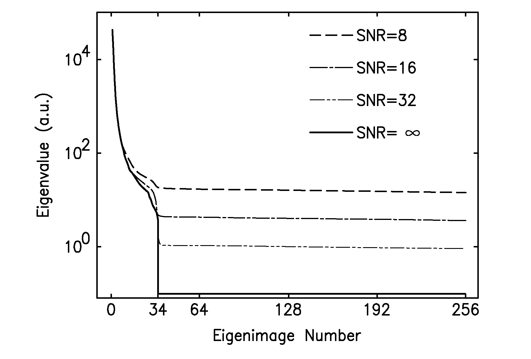
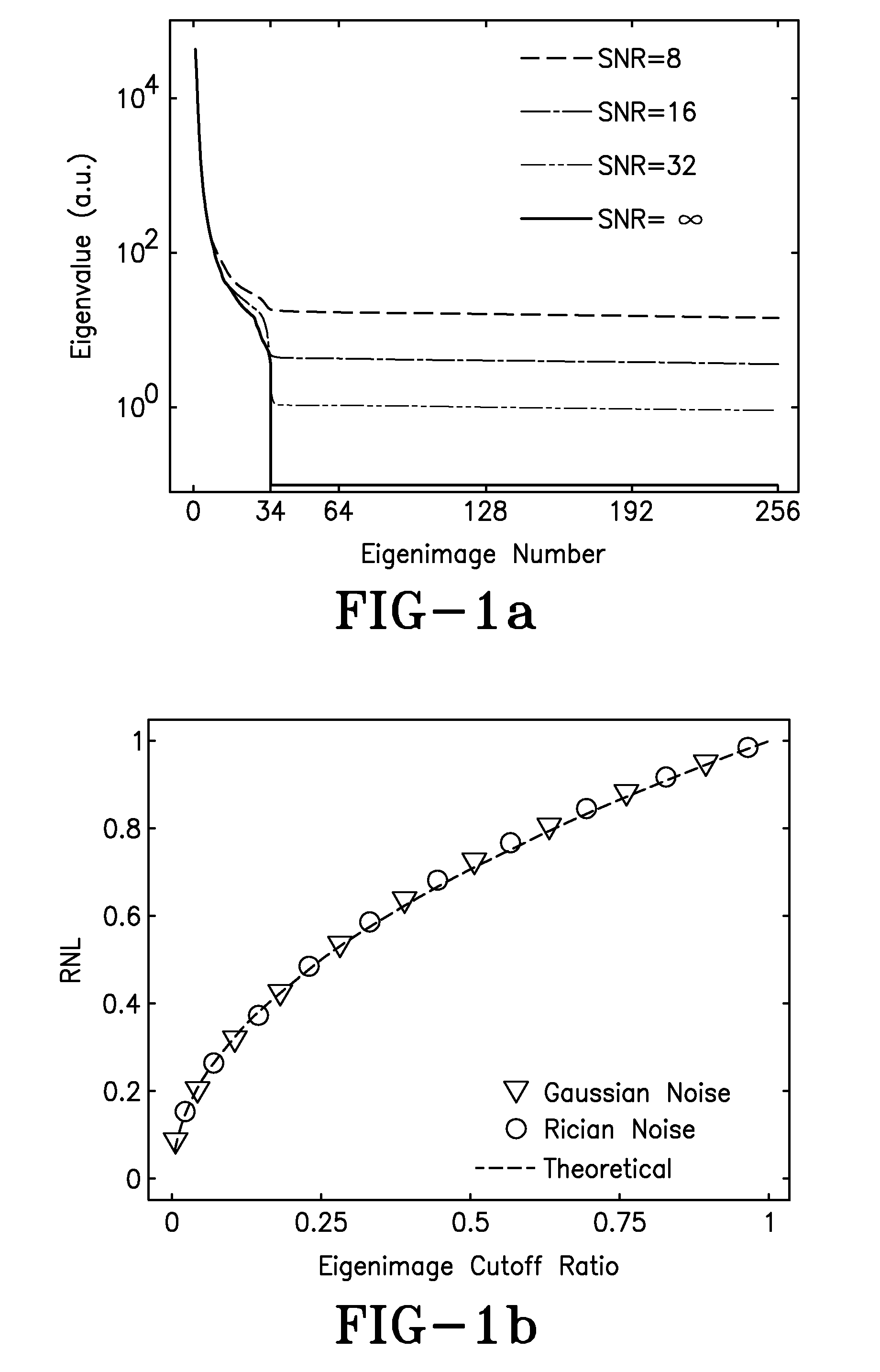
"The present invention is about a filter that uses the Karhunen-Loeve Transform (KLT) to denoise real-time dynamic magnetic resonance images. The KLT is an optimal signal compression method that reduces high dimensional data sets by exploiting signal correlations. The filter improves the signal-to-noise ratio in dynamic imaging and reduces noise while introducing minimal or no blurring to individual images. It is particularly useful for cardiac imaging and can be applied to any dynamic data set, including perfusion imaging of other organs or images acquired by other modalities. The filter automatically selects the optimal eigenimage cutoff to maximize noise reduction with minimal effect on image information. Overall, the KLT filter and method of use offer a feasible and practical solution to improve the SNR in highly-accelerated real-time dynamic cardiac MRI."

Problems solved by technology

In prior methods using noise reduction by KLT filters for cardiac imaging applications, images of the heart were limited to one single cardiac cycle.
While the images within one heartbeat are correlated, redundancy is limited because the heart changes shape from one image frame to the next.
Although KLT filters have been proposed for other medical imaging applications, the details of KLT image-filter design have not been well addressed.
More specifically, the choice of eigenimage cutoff and its effect on SNR gain and image sharpness have not been fully understood.
The lack of such knowledge may result in a suboptimal use of an optimal transform filter.

Method used


Image

  • System and method for improved real-time cine imaging
  • System and method for improved real-time cine imaging
  • System and method for improved real-time cine imaging

Examples


Embodiment Construction

)

[0031]A temporal series of p two-dimensional images, each with N pixels, can be represented as the matrix {Ai}, where i=1, . . . , p. Each Ai represents a 1-D, N-point vector containing all of the pixel values for a single image. The mean is subtracted from each Ai, and the KLT proceeds as follows.

[0032]Let⁢⁢matrix⁢⁢A⁢⁢(dimension⁢⁢A=[A1A2⋮Ap],(1)

[0033]Its corresponding p×p co-variance matrix C is

C=AAH / (N−1)   (2)

[0034]where AH is conjugate transpose of A.

[0035]C has p distinct eigenvalues λ1>λ2> . . . >λp, with corresponding eigenvectors v1, v2, . . . , vp. A p×p matrix E can be constructed using p eigenvectors derived from C as rows:

[0036]E=[v1v2⋮vp].(3)

[0037]Note that E is a unitary matrix, and E1=ET.

[0038]The p×N-point dynamic data sets {Ai} may be transformed by E to another p×N-point data sets {Bi} represented by the p×N matrix B:

[0039]B=[B1B2⋮Bp],(4)

[0040]where,

B=E·A  (5)

[0041]The matrix E is the Karhunen-Loeve Transform for A. Unlike {Ai}, every N-point data set in {Bi} is o...


PUM


Abstract

A cine imaging filter and method of use that includes a denoising image-filter based on the Karhunen-Loeve transform along the temporal direction to take advantage of the high temporal correlation among images. The cine imaging filter may further include the application of a simple formula describing the quantitative noise reduction capabilities of the KLT filter as a function of eigenimage cutoff. Additionally, the filter may validate its accuracy in numerical simulation and in in-vivo real time cine images. Furthermore, exemplary embodiments of the cine imaging filter may employ a technique to automatically select the optimal eigenimage cutoff to maximize noise reduction with minimal effect on image information.

Description

CROSS REFERENCES TO RELATED APPLICATIONS[0001]This application claims priority to U.S. Provisional Patent Application Ser. No. 61 / 045,786, filed Apr. 17, 2008, which is incorporated by reference as if fully recited herein.FIELD OF THE INVENTION[0002]The present invention relates systems and methods for dynamic imaging. In particular, the present invention is directed to a system and method for improving dynamic imaging by applying a Karhunen-Loeve Transform Filter to improve signal to noise ratio or temporal resolution in dynamic imaging.BACKGROUND OF THE INVENTION[0003]In magnetic resonance imaging (MRI), the requirements for acquisition speed (or temporal resolution), spatial resolution and signal-to-noise ratio (SNR) often compete with each other. This competition is especially apparent in real-time MRI where spatial resolution and SNR performance may be sacrificed to achieve the temporal resolution needed to capture dynamic physiological events. For example, parallel imaging tec...

Claims


Application Information

Patent Timeline
Patent Type & Authority Patents(United States)
IPC IPC(8): G06K9/00
CPCG06T5/002G06T5/007G06T2207/10076G06T2207/20182G06T2207/30048G06T2207/10088G06T5/70G06T5/90
Inventor DING, YUSIMONETTI, ORLANDO P.CHUNG, YIU-CHO
Owner THE OHIO STATE UNIV RES FOUND
Learn More