
System and method for geometry shading

a geometry shader and geometry technology, applied in the field of graphics processing, can solve the problems of increasing latency, reducing the memory required to store both the input primitives and output primitives increasing the time required for the execution of the geometry shader, so as to reduce the time required for sequential draining the resulting output buffer, the memory required to implement the algorithm, and the effect of reducing the total memory required

Active Publication Date: 2012-07-03
NVIDIA CORP
View PDF5 Cites 18 Cited by
  • Summary
  • Abstract
  • Description
  • Claims
  • Application Information

AI Technical Summary

Benefits of technology

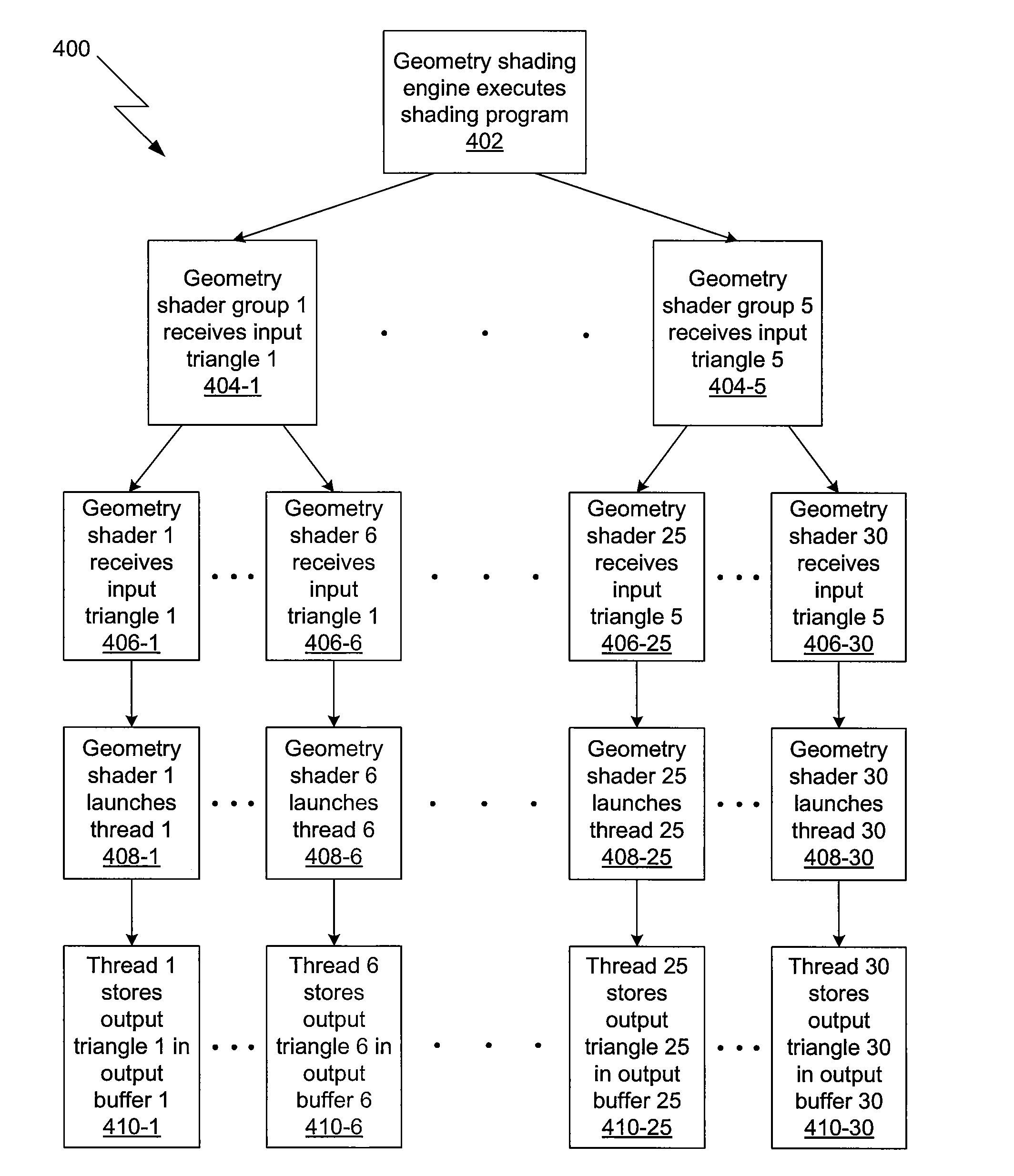
[0015]One advantage of the disclosed method is that, since the overall work associated with a given input primitive is distributed across multiple geometry shaders, the output of each geometry shader is smaller and, thus, the total memory required to implement the algorithm is reduced. Another advantage is that, since both the time required for the geometry shaders to execute and the time required to sequentially drain the resulting output buffers are reduced, the latency of the geometry shaders are also reduced.

Problems solved by technology

One drawback to using geometry shaders, however, is that the memory required to store both the input primitives and the output primitives of the geometry shaders is expensive because the on-chip memories take up valuable die area.
Another drawback is that the latency of the geometry shaders may be large.
However, since accessing off-chip memory is slower than accessing on-chip memory, such a solution will further increase the latency of the geometry shaders and, thus, may cause the geometry shaders to become a bottleneck in the graphics pipeline.
Again, the on-chip memory will be expensive, and accessing the off-chip memory may cause the geometry shaders to become a bottleneck in the graphics pipeline.

Method used


Image

  • System and method for geometry shading
  • System and method for geometry shading
  • System and method for geometry shading

Examples


Embodiment Construction

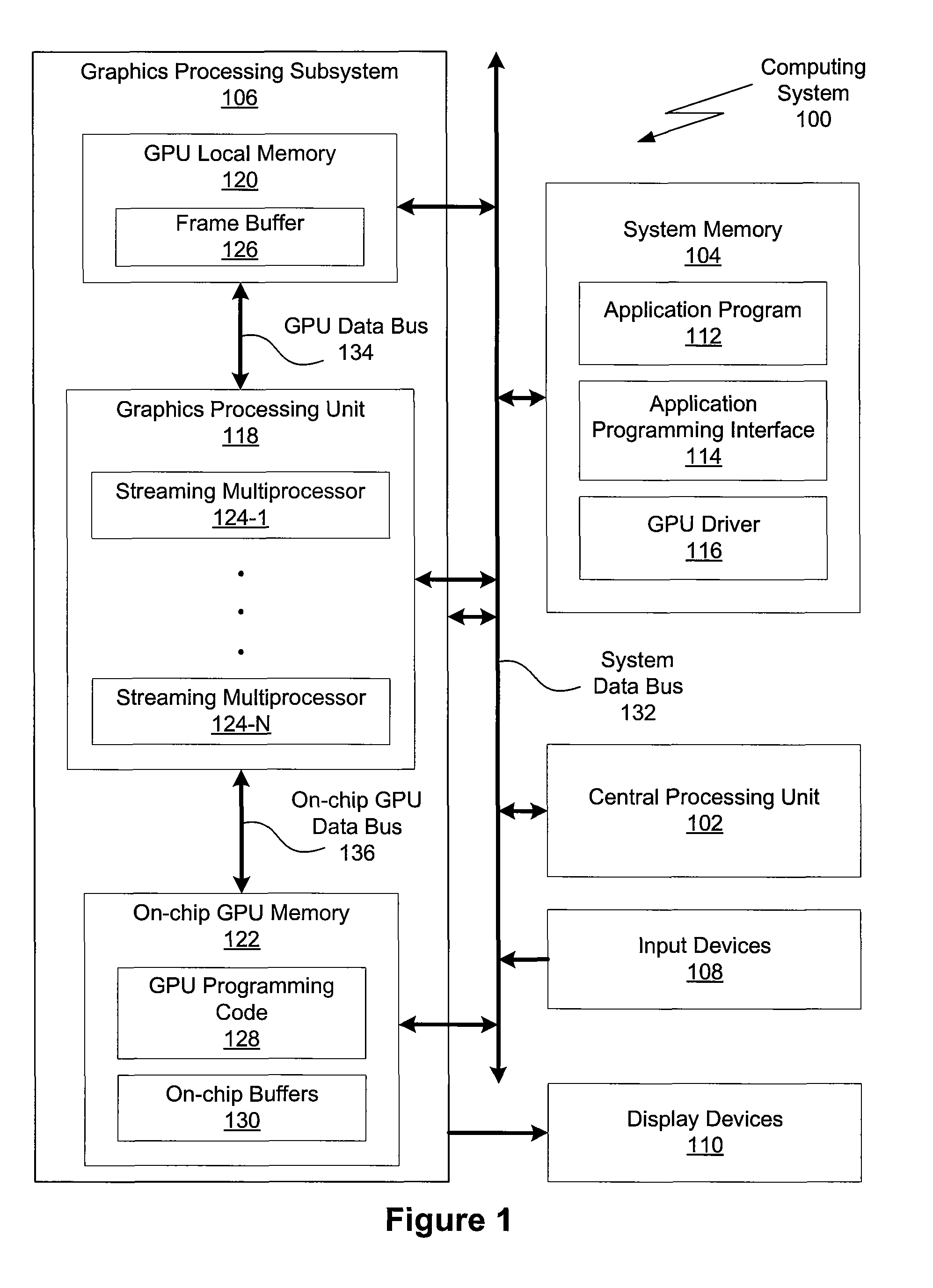
[0022]FIG. 1 is a conceptual diagram of a computing system 100 in which one or more aspects of the invention may be implemented. The computing system 100 includes a system data bus 132, a central processing unit (CPU) 102, input devices 108, a system memory 104, a graphics processing subsystem 106, and display devices 110. In alternate embodiments, the CPU 102, portions of the graphics processing subsystem 106, the system data bus 132, or any combination thereof, may be integrated into a single processing unit. Further, the functionality of the graphics processing subsystem 106 may be included in a chipset or in some other type of special purpose processing unit or co-processor.

[0023]As shown, the system data bus 132 connects the CPU 102, the input devices 110, the system memory 104, and the graphics processing subsystem 106. In alternate embodiments, the system memory 100 may connect directly to the CPU 102. The CPU 102 receives user input from the input devices 108, executes progr...


PUM


Abstract

One embodiment of the present invention sets forth a technique for more effectively utilizing graphics hardware by allowing the developer to exploit parallelism at the primitive-level. In this technique, an algorithm is analyzed to break the total work associated with processing one primitive into discrete portions of work. The results of this analysis are used to program a geometry shader group that includes multiple geometry shaders. Upon receiving a single input primitive, the geometry shader group launches multiple parallel threads, one thread in each geometry shader in the group corresponding to each discrete portion of work. As each thread completes, the output of the thread is stored in on-chip GPU memory for processing by the next stage in the graphics pipeline. Since the overall work associated with a given input primitive is distributed across multiple threads, the output of each thread is smaller and, thus, the total memory required to implement the algorithm is reduced.

Description

BACKGROUND OF THE INVENTION[0001]1. Field of the Invention[0002]The present invention relates generally to the field of graphics processing and more specifically to a system and method for geometry shading.[0003]2. Description of the Related Art[0004]A typical computing system includes a central processing unit (CPU), a system memory, a graphics processing unit (GPU), a GPU local memory, a GPU on-chip memory, one or more display devices, and one or more input devices. The CPU usually executes the overall structure of the software application and configures the GPU to perform specific tasks in the graphics pipeline (the collection of processing steps performed to transform 3-D images into 2-D images). Some GPUs are capable of very high performance using a relatively large number of small, parallel execution threads on dedicated programmable hardware processing units.[0005]To fully realize the processing capabilities of advanced GPUs, GPU functionality may be exposed to graphics appli...

Claims


Application Information

Patent Timeline
IPC IPC(8): G06F15/80
CPCG06T15/005G06T2210/52
Inventor EVERITT, CASS W.MORETON, HENRY PACKARD
Owner NVIDIA CORP
Learn More