
Hard-coated antiglare film, and polarizing plate and image display including the same

a technology of glare film and polarizing plate, which is applied in the direction of coatings, polarising elements, instruments, etc., can solve the problems of white blur, considerable reduction of contrast, and deterioration of image quality, so as to improve bright-dark contrast, reduce haze value, and prevent glare

Active Publication Date: 2012-07-10
NITTO DENKO CORP
View PDF16 Cites 6 Cited by
  • Summary
  • Abstract
  • Description
  • Claims
  • Application Information

AI Technical Summary

Benefits of technology

The solution significantly improves bright-dark contrast and prevents glare, allowing for high-definition displays with reduced haze value and minimized white blur, resulting in improved image display properties.

Problems solved by technology

In such high definition image displays, when a conventional hard-coated antiglare film is disposed, variations in brightness in pixels are emphasized further more to cause a visible failure (a failure due to glare) to result in considerably deteriorated image quality.
However, this method has a problem in that the contrast is decreased considerably because light is scattered intensively at the panel surface.
Furthermore, in the case where the surface unevenness is increased to improve antiglare properties, there is a problem in so-called white blur in an oblique direction, that is, white blur is observed due to excessively intensive scattering of reflected light when the panel surface is viewed from the oblique direction.
This, however, may cause scatter at the aggregates or may cause a fine pattern to appear in a hard-coated film.
Furthermore, although a method that is effective in improving a part of properties has been proposed (see, for instance, JP 2003-4903 A and JP 4001320 B), a method that is effective in solving all the three problems described above has not been found.

Method used


Image

  • Hard-coated antiglare film, and polarizing plate and image display including the same
  • Hard-coated antiglare film, and polarizing plate and image display including the same
  • Hard-coated antiglare film, and polarizing plate and image display including the same

Examples


example 1

[0126]A material for forming a hard-coating layer (“OPSTAR Z7540” (trade name), manufactured by JSR Corporation, solid content: 56% by weight, and solvent: butyl acetate / methyl ethyl ketone (MEK)=76 / 24 (weight ratio)) containing the component (A) was prepared in which silica nanoparticles (the aforementioned component (B)) formed by bonding inorganic oxide particles and an organic compound containing a polymerizable unsaturated group to each other were dispersed. The material for forming a hard-coating layer contained the components (A) and (B) in a weight ratio of the component (A) in total:component (B) of 2:3, where the component (A) was dipentaerythritol and isophorone diisocyanate polyurethane and the component (B) was silica fine particles (whose weight average particle size was 100 nm or smaller) whose surfaces had been modified with organic molecules. The cured film formed of the material for forming a hard-coating layer had a refractive index of 1.485. Five parts by weight ...

example 2

[0128]A hard-coated antiglare film of Example 2 was obtained in the same manner as in Example 1 except that the mixture was diluted so as to have a solid concentration of 45% by weight and a butyl acetate / MEK weight ratio of 3 / 1.

example 3

[0129]A hard-coated antiglare film of Example 3 was obtained in the same manner as in Example 1 except that the fine particles used herein were crosslinked acryl-styrene particles, “Techpolymer XX79AA” (manufactured by Sekisui Plastics Co., Ltd., with a weight average particle size of 5.0 μm and a refractive index of 1.505).


PUM

PropertyMeasurementUnit
thicknessaaaaaaaaaa
surface roughnessaaaaaaaaaa
lengthaaaaaaaaaa

Abstract

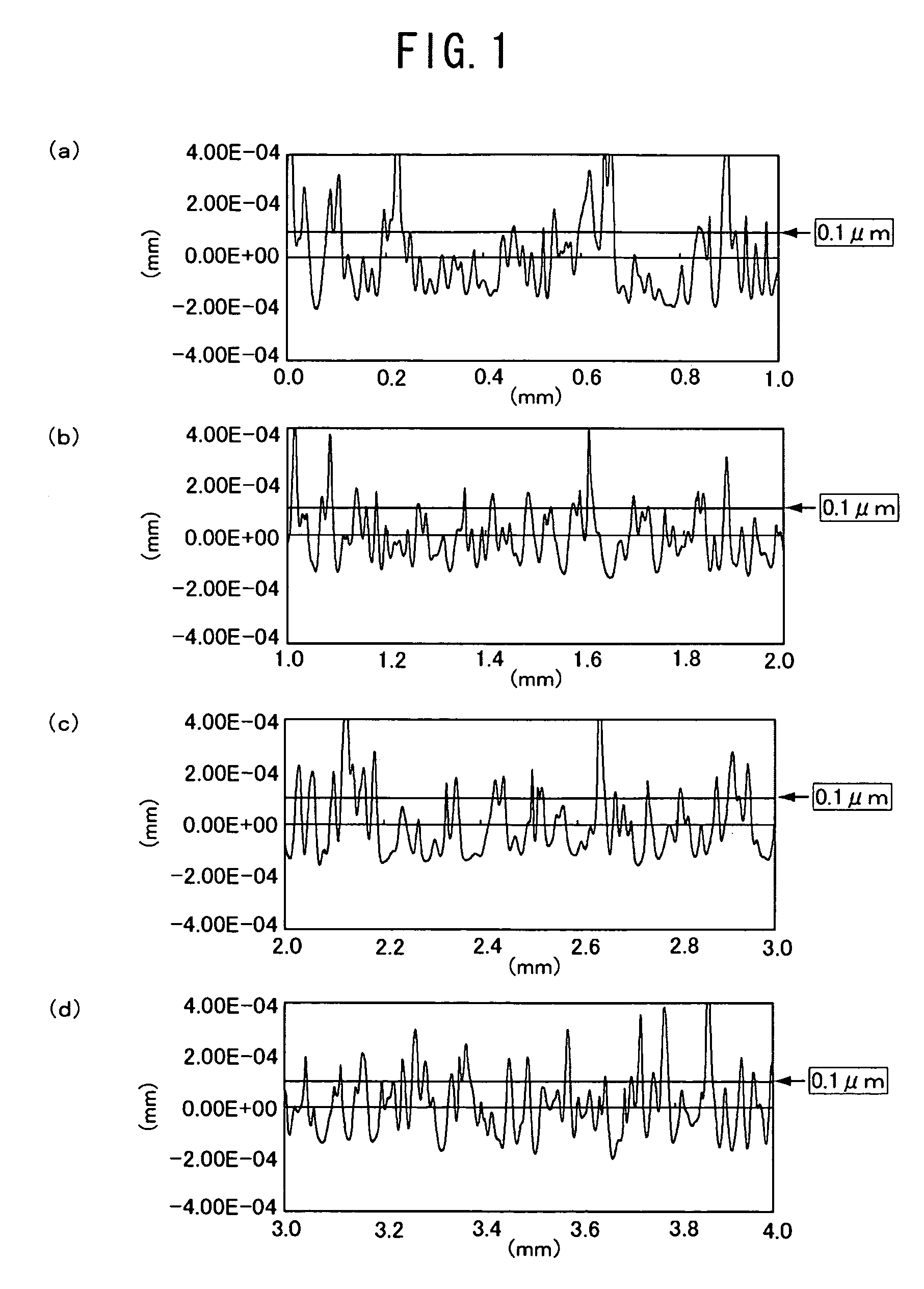
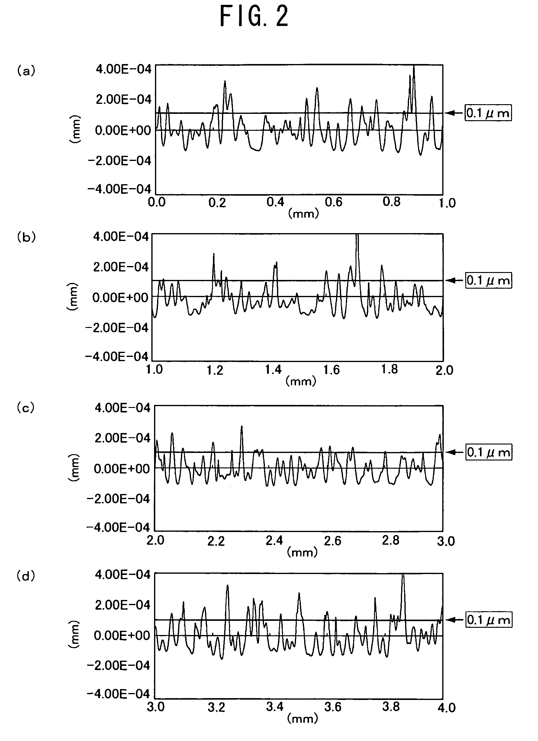
A hard-coated antiglare film, comprising a transparent plastic film substrate and a hard-coating antiglare layer containing fine particles on at least one surface of the transparent plastic film substrate, wherein an arithmetic average surface roughness Ra (μm) that is defined in JIS B 0601 (1994 version) is in the range of 0.05 to 0.15 μm in an uneven shape of a surface of the hard-coating antiglare layer, and the hard-coated antiglare film includes at least 80 convexities that exceed a roughness mean line of a surface roughness profile in a 4-mm long portion at an arbitrary location of the surface of the hard-coating antiglare layer.

Description

CROSS-REFERENCE TO RELATED APPLICATIONS[0001]This application claims priority from Japanese Patent Application Nos. 2008-092030 filed on Mar. 31, 2008 and 2008-142821 filed on May 30, 2008 the entire contents of which are hereby incorporated by reference.BACKGROUND OF THE INVENTION[0002]1. Field of the Invention[0003]The present invention relates generally to hard-coated antiglare films, and polarizing plates and image displays including the same.[0004]2. Description of the Related Art[0005]With technical improvements in recent years, liquid crystal displays (LCDs), plasma display panels (PDPs), electroluminescence displays (ELDs), etc. have been developed in addition to conventional cathode ray tube (CRT) displays as image displays and have been used in practical applications. Particularly, with technical innovations of LCDs with respect to, for example, wide viewing angles, high resolution, high response, and good color reproduction, applications of LCDs are spreading from laptop ...

Claims


Application Information

Patent Timeline
Patent Type & Authority Patents(United States)
IPC IPC(8): G02B27/00G02B1/10G02B1/11G02B1/111G02B1/115G02B1/14G02B5/02G02B5/30G02F1/1335
CPCG02B1/105G02B5/3033G02B5/02G02B1/14G02F1/1335G02B1/11
Inventor TSUNO, NAOKIHAMAMOTO, DAISUKEOZAWA, HIROKIKURAMOTO, HIROKI
Owner NITTO DENKO CORP
Learn More