Modified darrieus vertical axis turbine

a vertical axis turbine and darrieus technology, applied in vessel construction, renewable energy generation, greenhouse gas reduction, etc., can solve the problems of low overall low efficiency of towers, and low power efficiency of turbines

Active Publication Date: 2012-07-10
LUX
View PDF14 Cites 11 Cited by
  • Summary
  • Abstract
  • Description
  • Claims
  • Application Information

AI Technical Summary

Benefits of technology

[0016]By providing a plurality of blades, for example three or more, and more preferably five, which are supported by additional support members spanning under tension between adjacent blades in a horizontal direction, a minimum number of parts is required to form the structure of the blades while minimizing the drag produced during rotation thereof. The support members being connected horizontally only between adjacent blades when there are three or more blades results in the support members lying generally in a common peripheral or circumferential path during rotation so as to have minimal effect on drag. The tension of the support members can support the blades in a pre-stressed condition to optimize the shape and performance thereof. Furthermore, when arranged in a circumferential path between adjacent ones of the blades and at various heights along the blades, the support members provide support against centrifugal forces on the blades during rotation.
[0045]By forming the blades of a lift type turbine of segments in which the upper and lower segments form inclined lifting surfaces, a lower cost and simpler design of blade is produced while taking advantage of lift forces over the full length of the blade. Furthermore the portion of the blade at the outer periphery is increased to maximize the portion of the blade which is rotating at the periphery at optimum speed for maximizing efficiency.
[0068]By providing an annular frame member supporting the blades thereon, the blades have sufficient structural support that no central axle is necessarily required. Furthermore the annular frame member may be supported directly on a peripheral support in the form of rollers at fixed positions about the circumference of the rotor of the turbine to greatly simplify the support structure required. The annular frame member also permits a generator to be coupled at a periphery of the rotor of the turbine to minimize the complexity of the gearing required. When multiple annular frame members are provided, the resulting structure of the rotor, including the blades and the frame members upon which they are supported, is well supported regardless of whether or not a peripheral support system or a peripheral generator are provided.
[0073]There may be provided a brake for restricting rotation of the blades about the upright axis beyond an upper speed limit in which the brake is operatively connected to the base annular frame member.

Problems solved by technology

These wind turbines work for many years with little maintenance, however, they are very expensive.
These turbines tend to have lower overall power efficiency and have little advantage over the dominant horizontal axis turbines.
The towers are an expensive component and in most cases they limit the size of the turbine.
Use of various support arms and cables and the like to support the blades do not considerably affect the efficiency as the increased drag against rotation is partially offset by capturing more wind and due to the limited velocity of the turbine which is effectively limited to the speed of the wind.
Furthermore no additional structural support is provided to the blades along the length thereof which, in a lift type turbine, can be subjected to considerable centrifugal forces due to the high rotation speeds as well as strong lift forces towards the axis of rotation.
The sail portion of the blades are not suitably arranged to resist strong lifting forces being generated or strong centrifugal forces from high rotation speeds and accordingly the turbine has limited application.

Method used


Image

  • Modified darrieus vertical axis turbine
  • Modified darrieus vertical axis turbine
  • Modified darrieus vertical axis turbine

Examples


Embodiment Construction

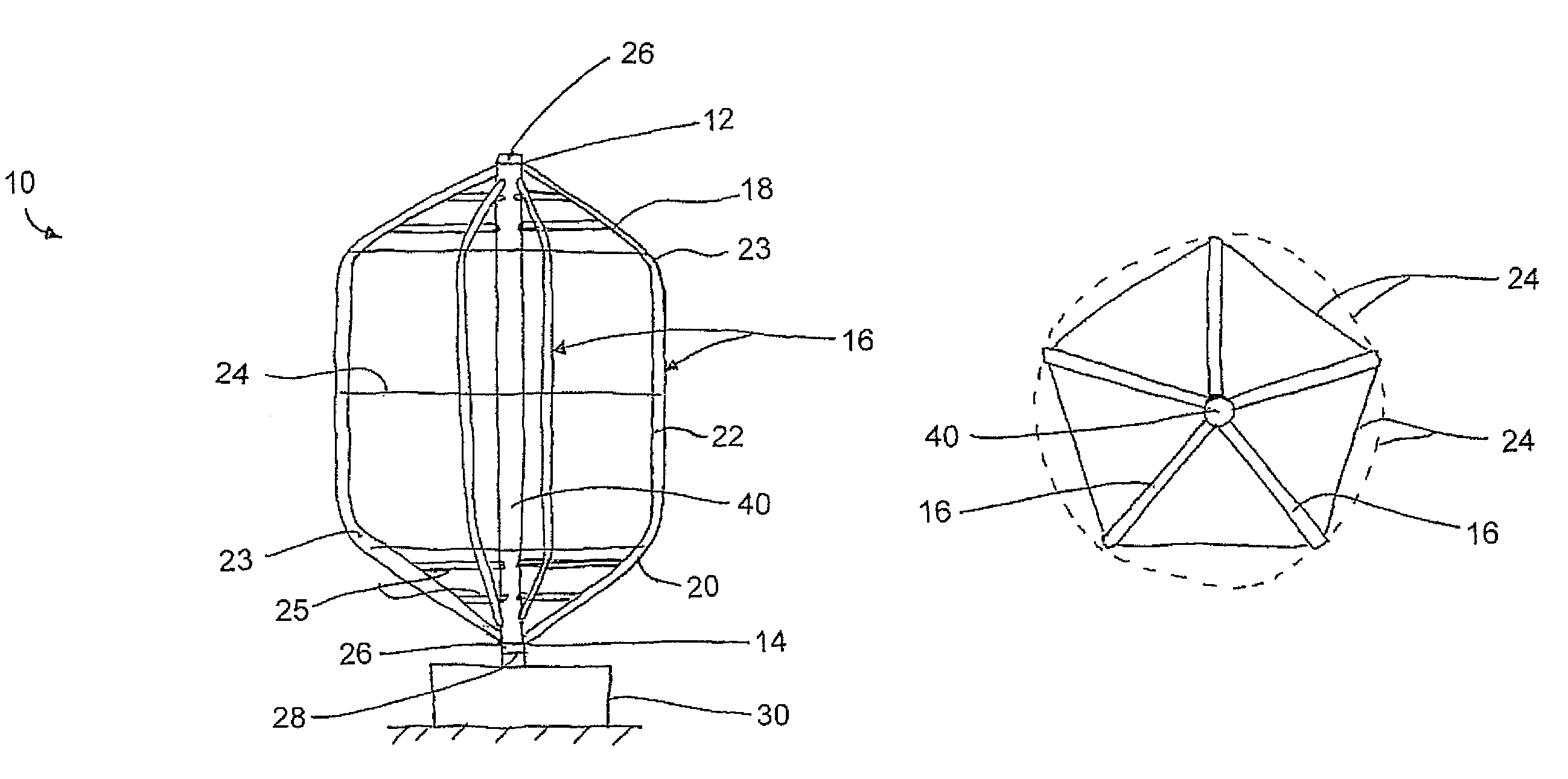
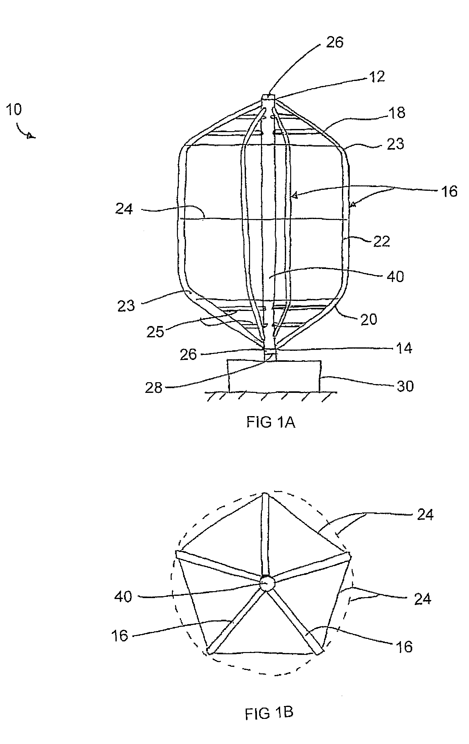
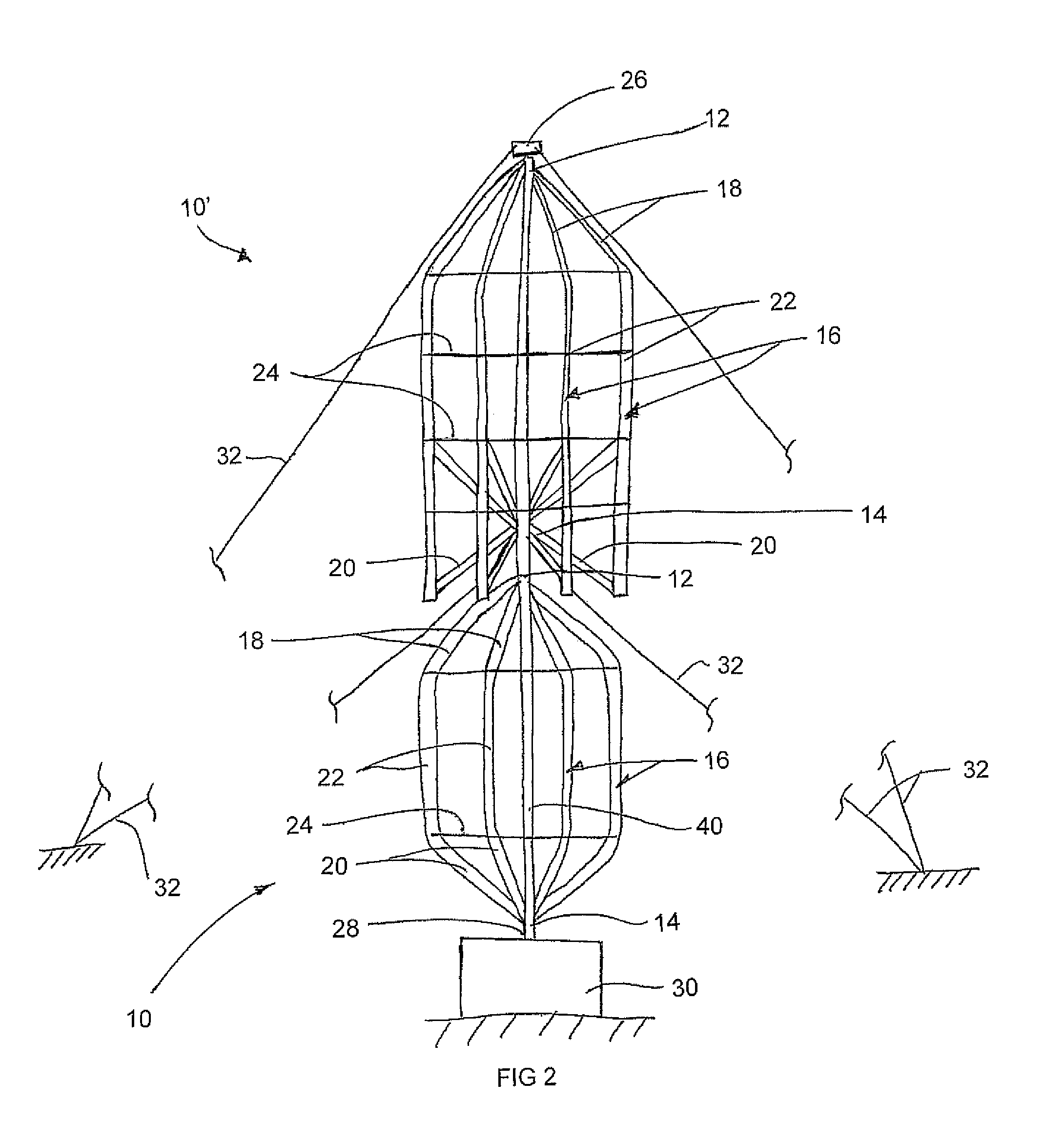
[0098]Referring to the accompanying figures there is illustrated a vertical axis lift type turbine generally indicated by reference numeral 10.

[0099]Although various embodiments of the turbine are described and illustrated herein, the common features of the first several embodiments will first be described herein.

[0100]The turbine 10 is supported for rotation about a vertical axis spanning between a top end 12 and a bottom end 14 of the turbine. The turbine includes a plurality of blades 16 spanning between the top and bottom ends of the turbine at evenly circumferentially spaced positions about the axis of rotation. The blades are all coupled to one another at the axis at both the top and bottom ends of the turbine. In the illustrated embodiments, a set of five blades are provided at an even spacing relative to one another.

[0101]Each blade 16 is formed of a plurality of blade segments which are assembled together at the time of manufacture. More particularly each blade includes a t...


PUM


Abstract

A lift-type turbine comprising at least three blades at circumferentially spaced positions is supported for rotation about a vertical axis. Each blade has an airfoil shape to generate a torque about the axis responsive to wind across the blades. A support comprising cables under tension is connected between adjacent ones of the blades to extend generally circumferentially about the turbine. Accordingly a minimum number of parts form the structure of the blades while minimizing the drag produced during rotation thereof due to the support members lying in a common circumferential path. The tension of the support members can support the blades in a pre-stressed condition to optimize the shape and performance thereof.

Description

[0001]This application claims the benefit under 35 U.S.C. 119(e) of U.S. provisional application Ser. No. 60 / 914,392, filed Apr. 27, 2007.FIELD OF THE INVENTION[0002]The present invention relates to a modified darrieus or lift type turbine in which the blades have a general airfoil like shape and are supported for rotation about a vertical axis.BACKGROUND[0003]Modern wind turbines are either horizontal axis turbines or vertical axis turbines. Horizontal axis wind turbines dominate the market world wide. They normally have a nacelle, rotor and blades that sit on top of a tower. The nacelle consists of the generator, planetary gearing and all the control systems necessary to operate the turbine. The rotor holds the blades (usually 3) in their positions while they rotate around the main shaft in the nacelle. These wind turbines work for many years with little maintenance, however, they are very expensive. The economics of horizontal axis wind turbines have been improving, but still nee...

Claims


Application Information

Patent Timeline
Patent Type & Authority Patents(United States)
IPC IPC(8): F03D1/02
CPCF03D3/065F05B2240/212F05B2240/214Y02E10/74F03D3/062
Inventor LUX
Owner LUX
Why Eureka
Try Eureka