Ponderomotive phase plate for transmission electron microscopes

a technology of transmission electron microscope and ponderomotive phase plate, which is applied in the field of ponderomotive phase plate system, can solve the problems of introducing problems of their own, loss of information at low spatial frequency and contrast reversals, so as to improve the existing cryo-tem system

Active Publication Date: 2012-07-10
LAWRENCE LIVERMORE NAT SECURITY LLC
View PDF4 Cites 11 Cited by
  • Summary
  • Abstract
  • Description
  • Claims
  • Application Information

AI Technical Summary

Benefits of technology

[0011]The PPP system includes two main components, including a laser source for producing a laser beam, and a beam transport system for transporting the laser beam into the TEM column as a focused laser crossover that is synchronized (with appropriate time delays for electron and photon propagation) to an electron beam propagating through the TEM column and aligned to intersect and partially overlap the electron beam emerging from a sample (i.e. post-sample electron beam) at a diffraction plane of a post-condenser lens system, so that the ponderomotive potential of the focused laser crossover causes a scattering-angle dependent phase shift in the scattered electrons of the post-sample electron beam. The laser source may be of a type that produces a pulsed laser beam, or a continuous wave (CW) laser. It is appreciated, however, that pulsed operation enables the laser to deliver higher powered laser beams, to achieve higher spatial and temporal resolution than CW operation.
[0015]Furthermore, a beam dump, preferably easily replaceable, may also be provided and positioned beyond the laser crossover in order to absorb the laser energy, preventing damage to the other parts of the TEM. Alternately, the laser is used to excite and maintain a standing wave in a resonant cavity with the appropriate spatial profile for the application.
[0016]As such, it is appreciated that unlike the prior art, the phase plate produced by the PPP system is not a physical structure, but is rather a virtual phase plate formed from the photons of the focused laser crossover, and not atoms. Thus by controlling a spatial profile of the laser crossover to control the ponderomotive potential, the phase-contrast transfer function of the TEM may likewise be controlled. In this manner, the invention is capable of producing all of the advantages of a conventional phase plate with none of the disadvantages. For example, since the phase plate is made of photons instead of atoms, it cannot accumulate contamination and it won't produce any significant incoherent scattering.
[0019]This PPP system and method can be used (e.g. in a modified DTEM) to achieve real-space imaging at currently impossible levels of spatiotemporal resolution for low-contrast samples such as biological materials. It could also be used for high-resolution high-contrast imaging of static biological samples, even without making use of the time resolution, by providing the benefits of a phase plate without the drawbacks of conventional phase plate designs. The PPPP could augment existing cryo-TEM systems. The PPP system could in principle also be used in a variety of non-standard operating modes, enabling very unusual two-dimensional contrast transfer functions, streak-camera-like operation, and (potentially) electron lens aberration correction including chromatic aberration correction in a picosecond TEM.

Problems solved by technology

Many of the prior art methods using a physical phase plate have significant drawbacks in terms of the CTF, such as the loss of information at low spatial frequencies and contrast reversals and oversensitivity to incoherence at high spatial frequencies.
Physical phase plates, which produce a 90 degree phase shift between low-angle and high-angle scattered electrons, can bypass some of these problems but introduce problems of their own.
For example, the physical phase plate itself can cause incoherent scattering, and intermediate spatial frequency information may be totally lost.
Moreover, the physical phase plate may experience contamination.

Method used


Image

  • Ponderomotive phase plate for transmission electron microscopes
  • Ponderomotive phase plate for transmission electron microscopes
  • Ponderomotive phase plate for transmission electron microscopes

Examples


Embodiment Construction

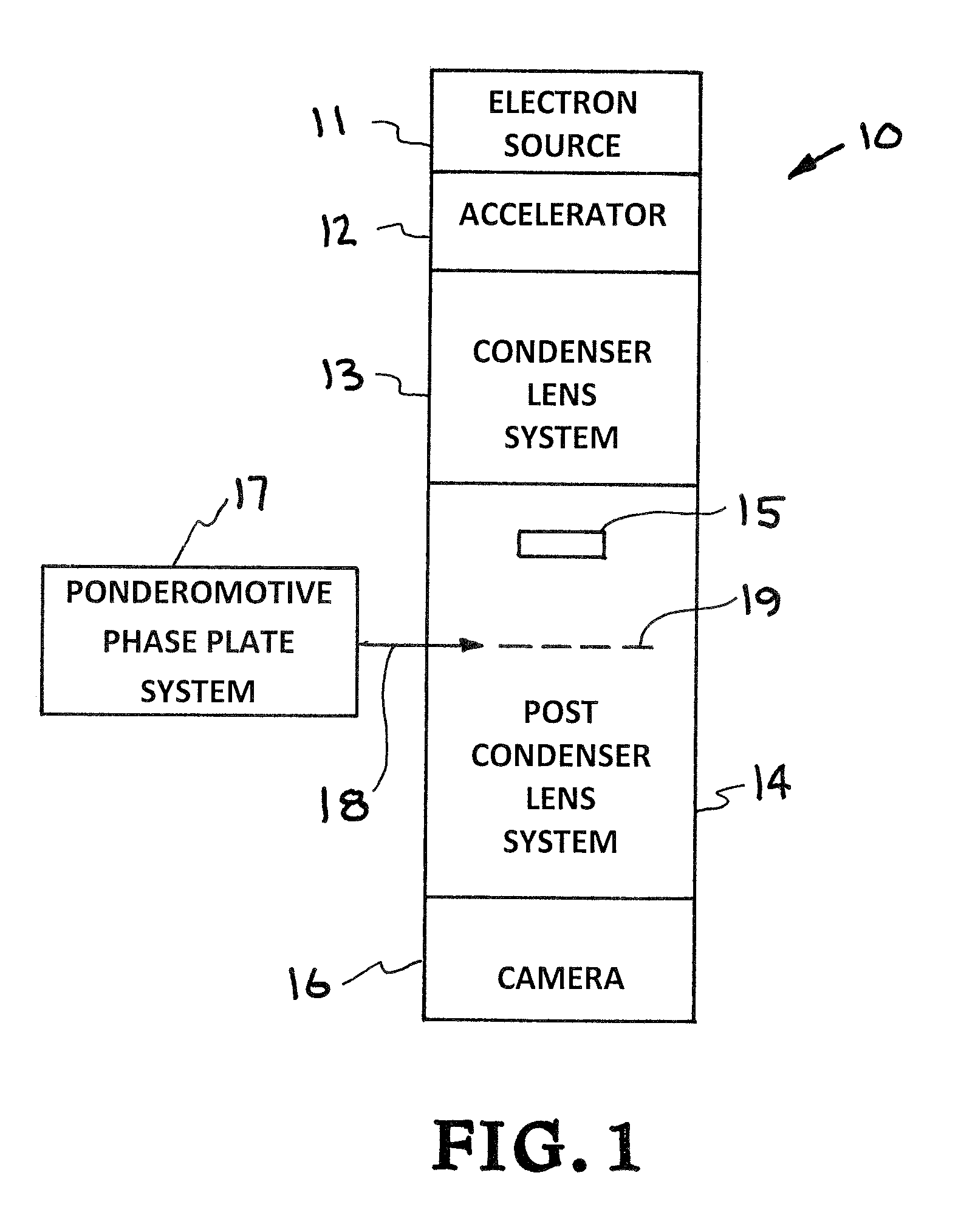
[0028]Turning now to the drawings, FIG. 1 shows a schematic view of a generalized first exemplary embodiment of an improved TEM of the present invention, generally indicated at reference character 10, and including a PPP system 17 integrated as a sub-system of the improved TEM. In the alternative, FIG. 1 may also be characterized as schematically showing the general case of how a PPP system 17 of the present invention may be used with and incorporated into existing TEM columns.

[0029]In either case, FIG. 1 schematically shows five basic TEM column modules known in the art and common to most TEM arrangements, including: an electron source 11, such as an electron gun, for producing an electron beam / bunch at a furthest upstream location, an accelerator 12 for accelerating the electron beam down the TEM column, a condenser lens system 13 for primary beam formation of the electron beam, a post-condenser lens system 14 for focusing the electron beam onto a sample and providing post-sample ...


PUM

PropertyMeasurementUnit
angleaaaaaaaaaa
angleaaaaaaaaaa
pulse energyaaaaaaaaaa

Abstract

A ponderomotive phase plate system and method for controllably producing highly tunable phase contrast transfer functions in a transmission electron microscope (TEM) for high resolution and biological phase contrast imaging. The system and method includes a laser source and a beam transport system to produce a focused laser crossover as a phase plate, so that a ponderomotive potential of the focused laser crossover produces a scattering-angle-dependent phase shift in the electrons of the post-sample electron beam corresponding to a desired phase contrast transfer function.

Description

CLAIM OF PRIORITY IN PROVISIONAL APPLICATION[0001]This application claims priority in provisional application filed on Sep. 11, 2009, entitled “Pulsed Ponderomotive Phase Plate (PPPP)” Ser. No. 61 / 241,792, by Bryan W. Green.I. FEDERALLY SPONSORED RESEARCH OR DEVELOPMENT[0002]The United States Government has rights in this invention pursuant to Contract No. DE-AC52-07NA27344 between the United States Department of Energy and Lawrence Livermore National Security, LLC for the operation of Lawrence Livermore National Laboratory.II. FIELD OF THE INVENTION[0003]The present invention relates to transmission electron microscopes (“TEM”), and more particularly to a ponderomotive phase plate system and method for use in a TEM as an integrated sub-system thereof which introduces a scattering angle-dependent phase shift in an electron wave based on the ponderomotive effect of a laser crossover beam at a diffraction plane downstream of an interrogated sample to produce highly tunable contrast tr...

Claims


Application Information

Patent Timeline
Patent Type & Authority Patents(United States)
IPC IPC(8): G01N23/04
CPCH01J37/04H01J37/26H01J2237/2482H01J2237/2614
Inventor REED, BRYAN W.
Owner LAWRENCE LIVERMORE NAT SECURITY LLC
Why Eureka
Try Eureka