
Method and apparatus for processing a substrate using plasma

a substrate and plasma technology, applied in the direction of photomechanical equipment, instruments, fluid pressure measurement, etc., can solve the problems of increasing the rf power of the generated plasma, affecting the rf power of the higher frequency rf signal, and the thinnest photo resist layer being more susceptible to being inadvertently etched away

Active Publication Date: 2012-07-17
LAM RES CORP
View PDF25 Cites 0 Cited by
  • Summary
  • Abstract
  • Description
  • Claims
  • Application Information

AI Technical Summary

Benefits of technology

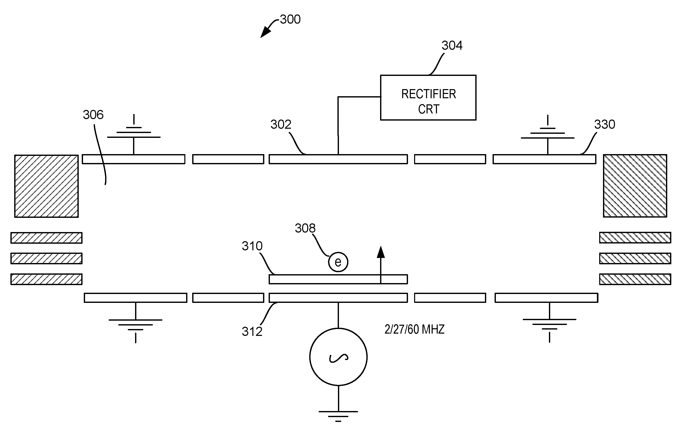
The invention is about a method for processing a substrate in a plasma processing system. The method involves using a first RF signal to induce a second RF signal on the upper electrode, which then processes the substrate. The first RF signal is rectified to create a more positive bias. The technical effect of this method is to improve the uniformity and quality of plasma processing for substrates.

Problems solved by technology

The thinner photo resist layer, in turn, tends to be more susceptible to being inadvertently etched away.
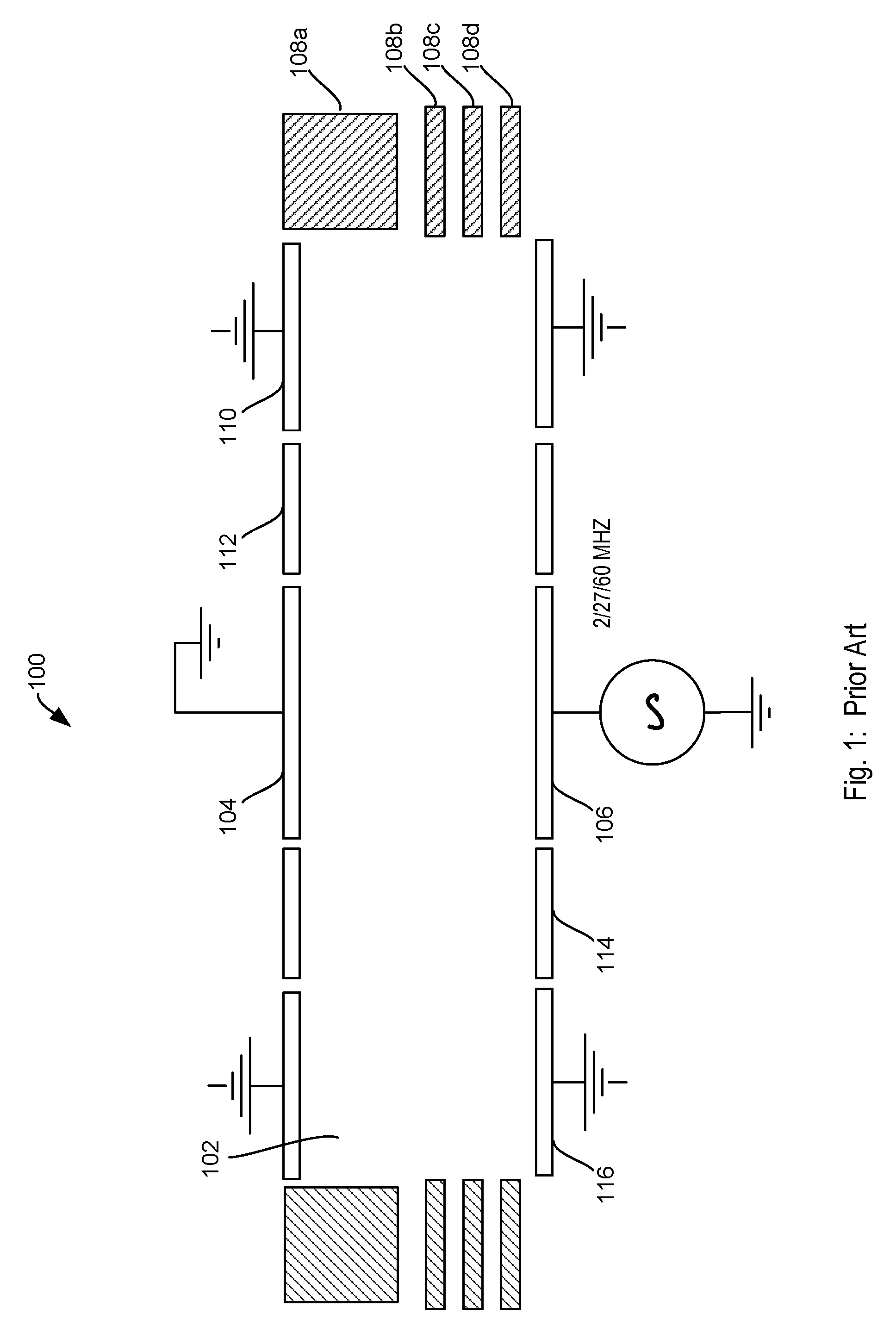
However, by increasing the power level of the higher frequency RF signals (e.g., the 27 Megahertz RF signal or the 60 Megahertz RF signal of FIG. 1), it may be challenging to confine the generated plasma within chamber 102.
Furthermore, increasing the RF power to the higher frequency RF signals has been found to adversely affect the photo resist selectivity.
At a high RF power level, the photo resist mask is damaged to a greater extent due to increased bombardment, which causes the photo resist mask to erode away at a faster rate, thereby negatively impacting the etching process.
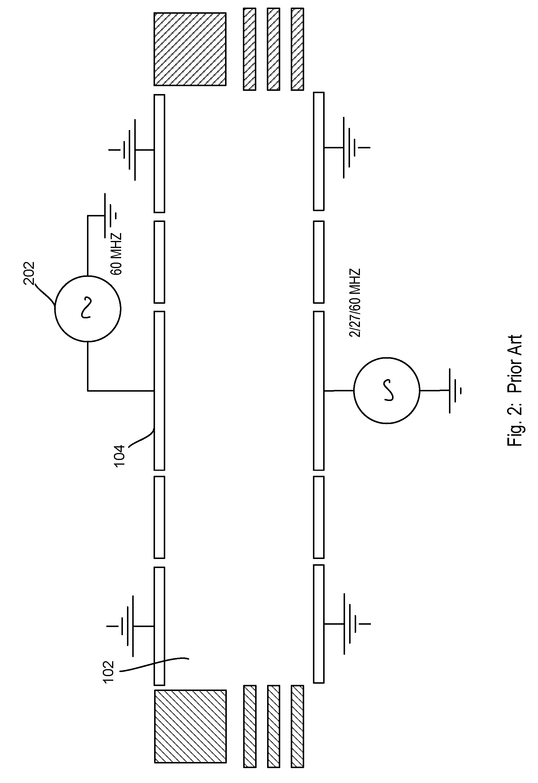
However, the implementation of FIG. 2 still does not solve the aforementioned problem of plasma density saturation point effect.
It has been found that the approach of controlling the temperature of the electrodes is minimally effective in controlling the photo resist selectivity.
Furthermore, the approach of controlling the temperature of the electrodes does not address the aforementioned problem of plasma density saturation point effect.
Therefore, various aforementioned prior art implementations have proven ineffective in increasing etch rate without adversely affecting or maintaining high photo resist selectivity in capacitively-coupled plasma processing system in processes that involve the etching of materials using a photo resist mask.
In the prior art implementation of FIG. 1, the increase in RF power to the lower electrode may lead to unconfinement of plasma, saturation point of plasma density, and adversely affect the photo resist selectivity.
Furthermore, the prior art implementation of controlling temperature of the electrodes is minimally effective in controlling the photo resist selectivity while providing no solution for the plasma density saturation effect.

Method used


Image

  • Method and apparatus for processing a substrate using plasma
  • Method and apparatus for processing a substrate using plasma
  • Method and apparatus for processing a substrate using plasma

Examples


Embodiment Construction

[0024]The present invention will now be described in detail with reference to a few embodiments thereof as illustrated in the accompanying drawings. In the following description, numerous specific details are set forth in order to provide a thorough understanding of the present invention. It will be apparent, however, to one skilled in the art, that the present invention may be practiced without some or all of these specific details. In other instances, well known process steps and / or structures have not been described in detail in order to not unnecessarily obscure the present invention.

[0025]Various embodiments are described hereinbelow, including methods and techniques. It should be kept in mind that the invention might also cover articles of manufacture that includes a computer readable medium on which computer-readable instructions for carrying out embodiments of the inventive technique are stored. The computer readable medium may include, for example, semiconductor, magnetic, ...


PUM

PropertyMeasurementUnit
RF frequencyaaaaaaaaaa

Abstract

Methods and arrangements for controlling the electron loss to the upper electrode, including techniques and apparatus for biasing the upper electrode more negatively to allow charged species to be trapped within the plasma chamber for a longer period of time, thereby increasing the plasma density may be increased. The induced RF signal on the upper electrode is rectified, thus biasing the upper electrode more negatively. The rectified RF signal may also be amplified, thus driving the upper electrode even more negatively, if desired.

Description

CROSS REFERENCE TO RELATED APPLICATIONS[0001]The present invention is related to the following applications, all of which are incorporated herein by reference:[0002]Commonly assigned application Ser. No. 11 / 618,583 entitled “Plasma-Enhanced Substrate Processing Method and Apparatus”, filed on even date herewith by the same inventors. BACKGROUND OF THE INVENTION[0003]In the processing of semiconductor substrates, plasma processing is often employed. Plasma processing may involve different plasma-generating technologies, for example, inductively-coupled plasma processing systems, capacitively-coupled plasma processing systems, microwave-generated plasma processing systems, and the like. Manufacturers often employ capacitively-coupled plasma processing systems in processes that involve the etching of materials using a photo resist mask.[0004]Important consideration for plasma processing of substrates involves a high etch rate and a high photo resist selectivity. A high etch rate refers...

Claims


Application Information

Patent Timeline
Patent Type & Authority Patents(United States)
IPC IPC(8): H01L21/302
CPCH01J37/32091H01J37/32532H01J37/32165H01L21/3065G03F7/427H01J37/32128H01J37/32174H01L21/306H01L21/31138
Inventor DHINDSA, RAJINDRAERIC, HUDSONMARAKHTANOV, ALEXEIFISCHER
Owner LAM RES CORP
Learn More