System for management and prevention of venous pooling

a venous pooling and management system technology, applied in the field of artificial stimulation of flow, can solve the problems of increased venous pressure, poor calf muscle pump function, and venous valve breakdown, and achieve the effect of minimizing venous pooling

Active Publication Date: 2014-10-09
THE NAT UNIV OF IRELAND GALWAY +1
View PDF8 Cites 31 Cited by
  • Summary
  • Abstract
  • Description
  • Claims
  • Application Information

AI Technical Summary

Problems solved by technology

Pooling of venous blood in the lower leg is a major contributory factor in the development of chronic venous insufficiency (CVI) which can result from breakdown of the venous valves and / or poor calf muscle pump function.
It leads to blood pooling in the veins resulting in increased venous pressure.
This increased pressure results in: pain, swelling, oedema, skin changes, varicose veins, deep vein thrombosis and venous leg ulcers.
Venous leg ulcers are the most severe and costly manifestation of CVI and are an enormous problem for both patients and healthcare providers.
However, compression hosiery is limited by poor compliance and has not been demonstrated to slow the progression of varicose veins.
Despite being the current gold standard treatment for venous leg ulcer care, this treatment modality doesn't allow the clinician to fully address the underlying cause of venous leg ulcers—blood pooling.
Individuals who are predisposed to prolonged venous pooling and CVI currently have very limited options to prevent the progression of symptoms of CVI.
Furthermore, clinicians treating this condition are not able to closely monitor the status of venous pooling in these patients and the treatment regimen is based on changes in the severity of the symptoms of this pooling—swelling and ulceration.
However, CVI patients are typically unable to maintain healthy muscle pump function, due to a sedentary lifestyle and exercise is often painful.
These cuffs are bulky and difficult to apply and consequently they may not be suitable for long term use such as CVI prevention.

Method used


Image

  • System for management and prevention of venous pooling
  • System for management and prevention of venous pooling
  • System for management and prevention of venous pooling

Examples


Embodiment Construction

Brief Description of the Drawings

[0067]The invention will be more clearly understood from the following description of some embodiments thereof, given by way of example only with reference to the accompanying drawings in which:—

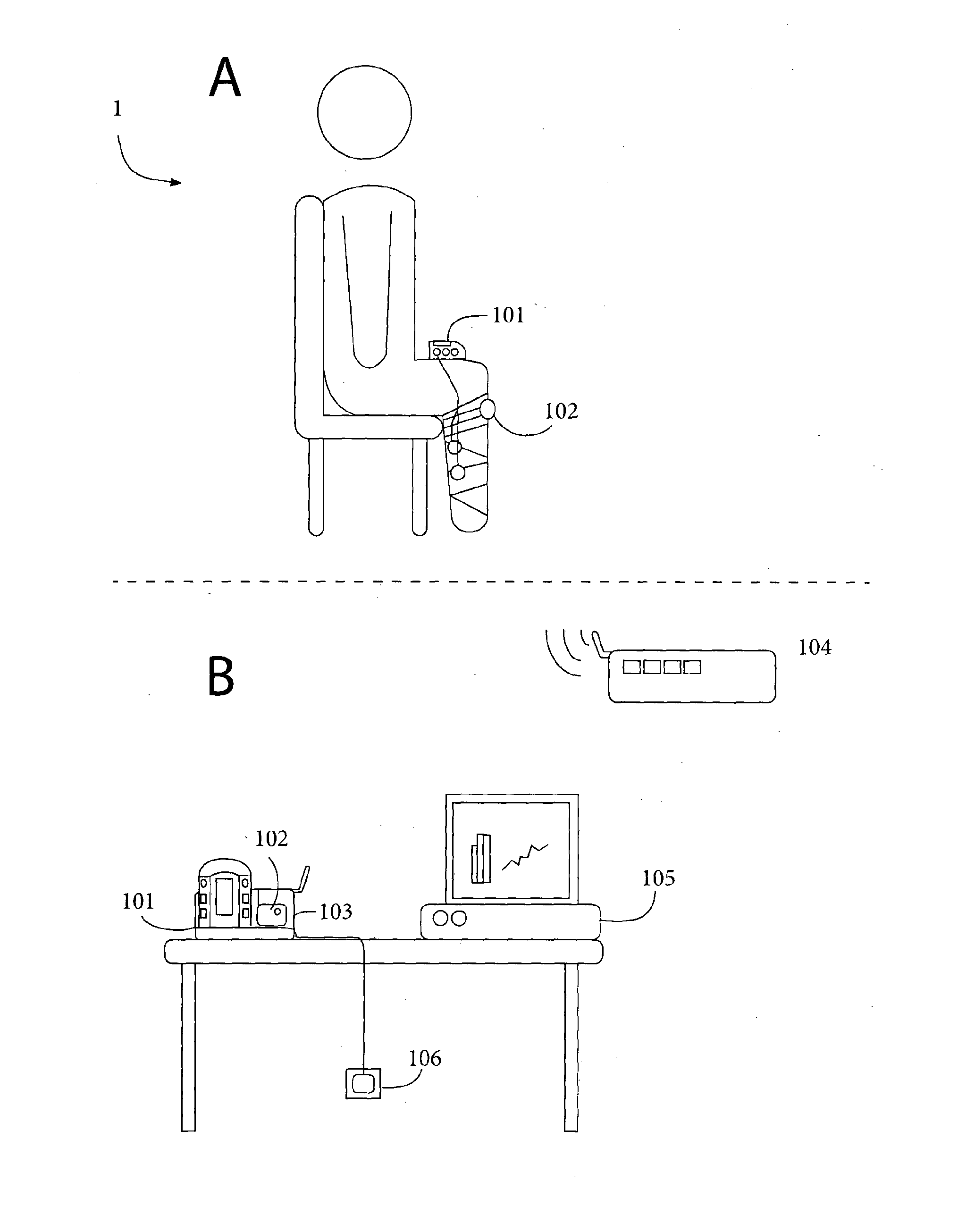
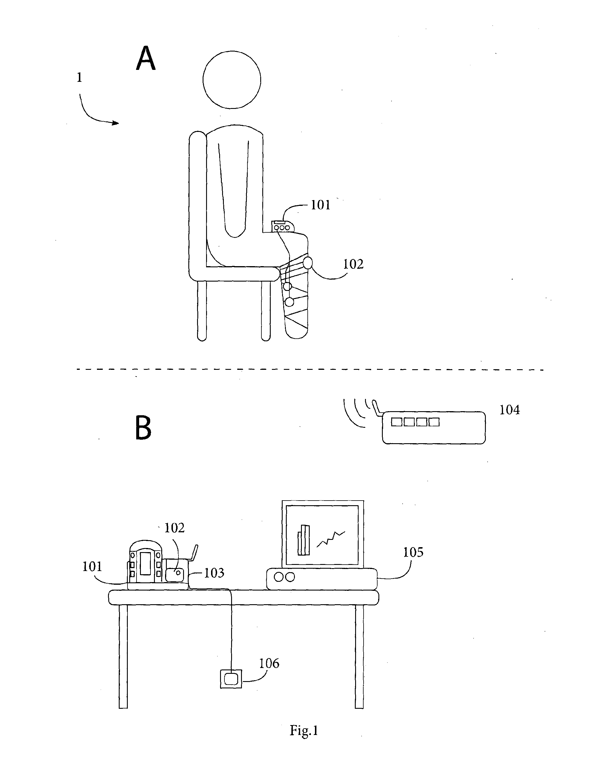
[0068]FIG. 1 is a general overview of the main components of a system of the invention in use;

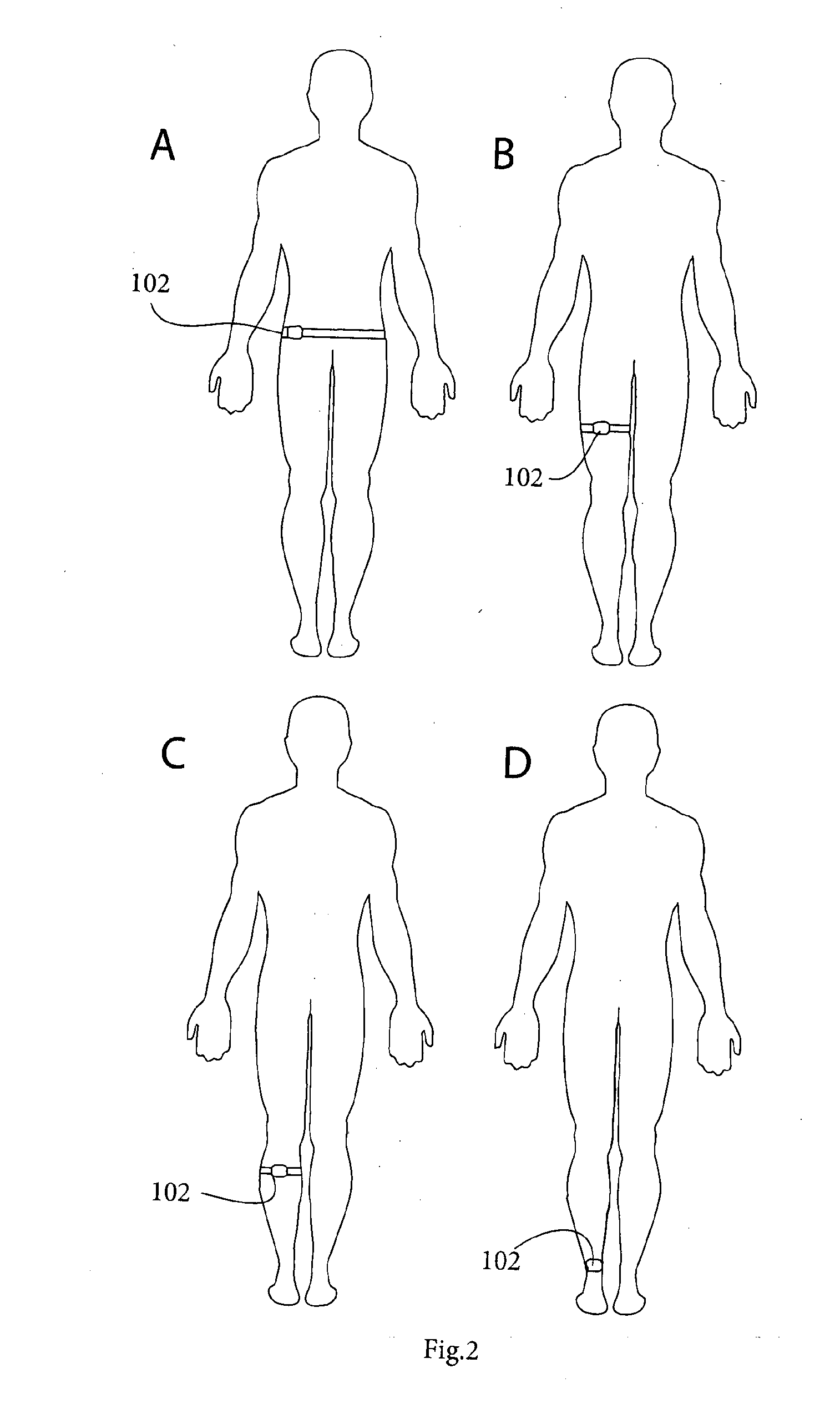
[0069]FIG. 2 shows possible locations for wearing sensors on the trunk and legs;

[0070]FIG. 3 is a functional block diagram of a sensor unit of the system;

[0071]FIG. 4 shows sensors incorporated into a garment;

[0072]FIG. 5 shows one possible configuration for the enclosure of the sensor unit;

[0073]FIG. 6 is a diagram showing how static venous pressure is calculated using postural data joint angles determined from sensors;

[0074]FIG. 7 shows two postures illustrating a postural transition from sitting to standing and the corresponding venous pressure waveform;

[0075]FIG. 8 is a flow diagram for the system controller to generate an alert based on a determination of venous...


PUM


Abstract

A monitoring system comprises sensors adapted to be worn by a user, and, a processor linked with the sensor. The processor receives sensor data and processes this data to determine user posture data including data indicative of vertical distance between level of the user's heart and ankle. Based on the posture data together with a value for degree of user chronic venous insufficiency and / or blood density, generate an estimate of user static venous pressure while the user is static, without calf muscle pump activity. The processor also processes the sensor data to determine if there is calf muscle pump activity, and generates an estimate of user active venous pressure according to the static venous pressure estimate, rate of calf muscle activity, and a value for degree of user chronic venous insufficiency. The processor may generate the venous pressure estimate in real time, and may control an NMES device accordingly.

Description

INTRODUCTION[0001]1. Field of the Invention[0002]The invention relates to artificial stimulation of flow from the leg and foot and specifically to its application for the prevention and treatment of chronic venous insufficiency (“CVI”).[0003]2. Prior Art Discussion[0004]In the healthy lower leg, blood flow in the veins must typically work against gravity to return to the heart. This unidirectional flow is facilitated by the presence of two mechanisms: venous valves and the calf muscle pump. Venous valves are located throughout the veins and maintain unidirectional flow towards the heart. During contraction, the calf muscles eject blood through the veins and back towards the heart. Both correctly functioning valves and healthy calf muscle pump function are essential for maintaining healthy venous flow and avoiding venous pooling.[0005]Pooling of venous blood in the lower leg is a major contributory factor in the development of chronic venous insufficiency (CVI) which can result from ...

Claims


Application Information

Patent Timeline
Patent Type & Authority Applications(United States)
IPC IPC(8): A61N1/36A61B5/00A61B5/11A61B5/0205A61B5/0295
CPCA61N1/36003A61B5/0205A61B5/0295A61B5/746A61B5/1118A61B5/6828A61B5/1116A61B5/02007A61B5/021A61B5/1071A61B5/1072A61B5/4836A61B5/6823A61B5/6829A61N1/36135
Inventor CORLEY, GAVINOLAIGHIN, GEAROIDBREEN, PAULBRODERICK, BARRYGRACE, PIERCE A.O'KEEFFE, DEREK
Owner THE NAT UNIV OF IRELAND GALWAY
Why Eureka
Try Eureka