Light pulse generating apparatus and cosmetic and therapeutic phototreatment

a technology of light pulses and generating apparatuses, which is applied in the field of apparatuses for producing light pulses, can solve the problems of difficult to find an energy level at which pulses will be effective, many limitations and problems in devices and methods, damage to skin or burns, etc., and achieves the effect of increasing the power loss in the electric driving circuit, easy to be kept away, and high intrinsic power loss

Inactive Publication Date: 2012-07-24
FOARD GEYSEN +1
View PDF77 Cites 9 Cited by
  • Summary
  • Abstract
  • Description
  • Claims
  • Application Information

AI Technical Summary

Benefits of technology

[0037]The generation of this kind of drive signal requires a different electric circuit, which operates with a higher intrinsic power loss compared to the circuits of the prior art. The invention therefore achieves the result referred to only at the cost of an increased power loss in the electric driving circuit. The shifting of the power loss to take place in the power supply unit rather in the optical filters is considered a major advantage, since power dissipated in the power supply unit may easily be kept away from the patient and from the sensitive optical components in the applicator.
[0038]The capability of the apparatus according to the invention of reducing the amplitude of the power output may be used to a substantial advantage. We have found that the skin epidermis is capable of dissipating a greater amount of energy input than the tissue in the hair follicle. Th

Problems solved by technology

We have found several limitations and problems in devices and methods according to the prior art.
Damage to the skin or burns occur very easily, making it difficult to find an energy level a

Method used


Image

  • Light pulse generating apparatus and cosmetic and therapeutic phototreatment
  • Light pulse generating apparatus and cosmetic and therapeutic phototreatment
  • Light pulse generating apparatus and cosmetic and therapeutic phototreatment

Examples


Embodiment Construction

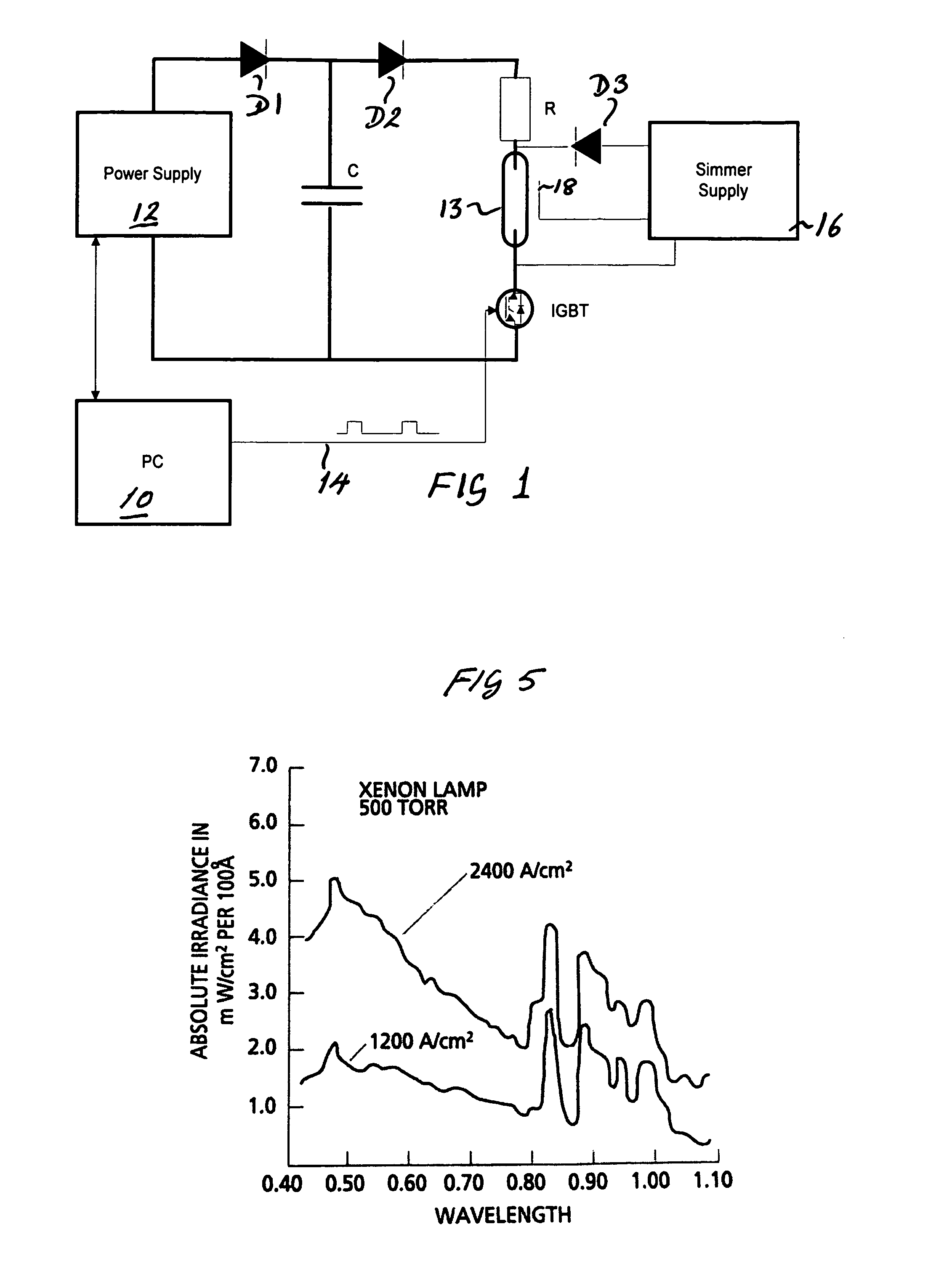
[0080]Reference is first made to FIG. 1 illustrating the driving circuit and the lamp.

[0081]The circuit in FIG. 1 comprises a control unit in the form of a personal computer 10 (PC) used to control the system. The PC is connected to a power supply 12 which is adapted to charge through the diode D1 the capacitor C. In a preferred embodiment the power supply is adapted to charge the capacitor to a voltage set from the PC to a level in the range from 100-1000 volts. In a preferred embodiment the capacitance of the capacitor C is 10 to 100 mF.

[0082]The capacitor C is connected through diode D2 and resistor R to the flash lamp 13. The circuit is completed by a solid state switch IGBT, which is in the preferred embodiment implemented in the form of an isolated gated bi-polar transistor. The IGBT is controlled from the PC by a line 14. The IGBT is capable of changing from non-conductive to conductive state, of carrying currents in the range of 500 A and of changing from conductive to non-c...


PUM


Abstract

Apparatus for therapeutic or cosmetic photo-treatment comprises a flash lamp and a lamp operating circuit. The lamp is cooled by water in contact with the lamp which acts as an infra-red filter to reduce skin burning. Light from the lamp reaches the skin through a light guide which has a convex curved end to focus the light and to press away haemoglobin in the target area or has a concave end to reduce pressure on the skin depending on the desired treatment. Relatively long and low power square shaped power pulses drive the lamp to produce light output pulses adapted to the relaxation time of the target structure to maximize the heating of the target while minimizing heating of the skin surface. Target structures may be blood vessels or hair follicles. Automatic detection of a glass filter may be provided.

Description

CROSS REFERENCE TO RELATED APPLICATIONS[0001]Not applicableSTATEMENT REGARDING FEDERALLY SPONSORED RESEARCH OR DEVELOPMENT[0002]Not applicableBACKGROUND OF THE INVENTION[0003]The present invention relates to apparatus for producing light pulses and to apparatus and methods using light for cosmetic or therapeutic photo-treatment.[0004]Apparatus of this type may be used for therapeutic purposes including treatment for psoriasis, vascular traumas, telangiectasis, capillary hemangioma, cancerous cells, port-wine stains, and birthmarks and also for depilation.[0005]WO 091 / 15264 describes a device for treatment of undesired skin disfigurements, which apparatus comprises a gas filled lamp and an optical filter. The lamp is powered by a capacitor charged to about 2,000 volts, which is sufficient for generating a pulse with a pulse duration between ½ and 1 ms.[0006]EP 0 565 331 A2 describes a therapeutic treatment device which includes a gas filled flash lamp and a set of optical filters. Th...

Claims


Application Information

Patent Timeline
IPC IPC(8): A61N5/06A61B17/00A61B18/00A61B18/18A61B18/20
CPCA61B18/203A61B2017/00172A61B2018/00023A61B2018/00452A61B2018/00458A61B2018/00476A61B2018/1807A61N5/0617
Inventor CHRISTIANSEN, KAREHANSEN, HUGIN
Owner FOARD GEYSEN
Why Eureka
Try Eureka