
Automatic gain control circuit

a gain control and circuit technology, applied in the direction of single-ended push-pull amplifiers, volume compression/expansion having semiconductor devices, code conversion, etc., can solve the problems of relatively and achieve the effect of constant signal-to-noise ratio (snr) and low cost of vga and gain controller

Active Publication Date: 2012-07-24
ELO TOUCH SOLUTIONS INC
View PDF31 Cites 52 Cited by
  • Summary
  • Abstract
  • Description
  • Claims
  • Application Information

AI Technical Summary

Benefits of technology

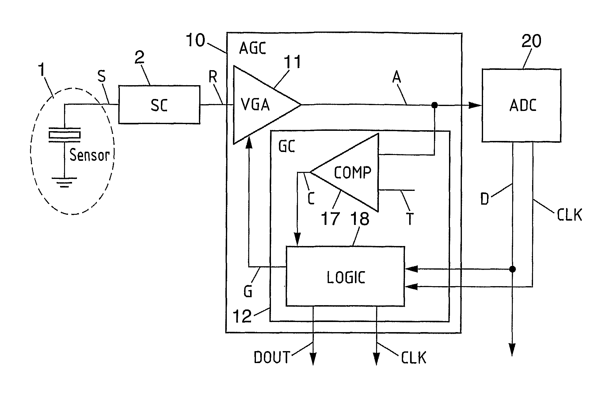
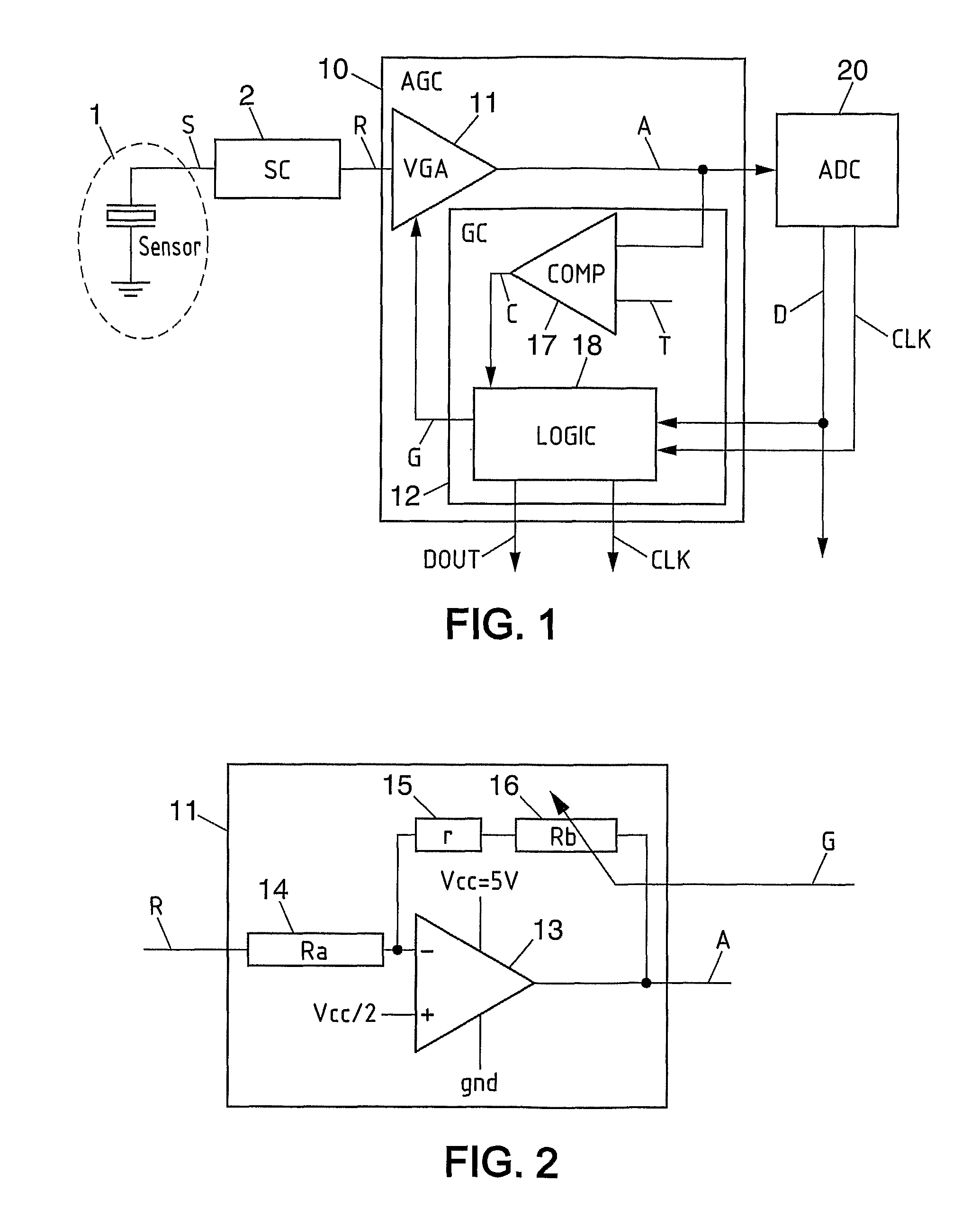
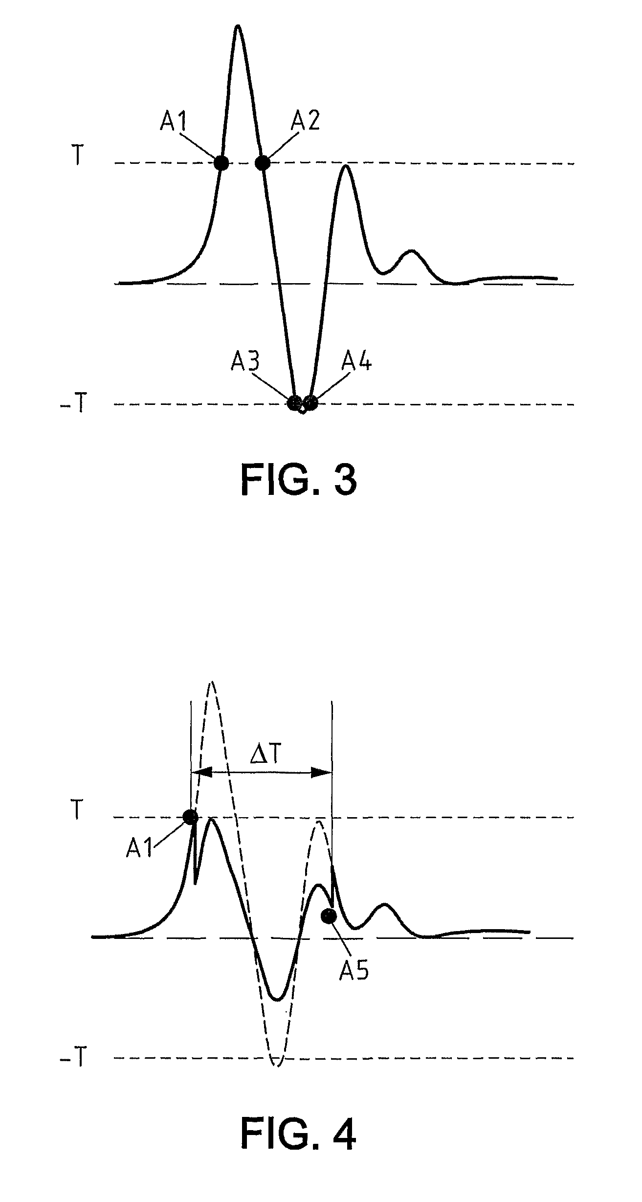
The present invention provides an efficient circuit for automatic gain control that does not require an integrator circuit. The gain controller is adapted to determine an occurrence of a threshold event each time the amplified signal has reached a predetermined threshold, decrease the gain of the variable gain amplifier at each occurrence of a threshold event, measure a delay since the last threshold event, increase the gain of the variable gain amplifier if the delay is greater than a delay specified value and if the gain of the variable gain amplifier is not maximum. This regulation of the gain of the VGA allows for anticipation of received signal amplitude change even during first impulses and results in a constant signal-to-noise ratio (SNR) in spite of change of received signal magnitude. The gain controller is relatively low-cost and can manage two channels, with two analog to digital converters and two variable gain amplifiers each in one or two circuits. The system may also include an analog to digital converter connected to the automatic gain control circuit and a vibration sensor connected to the variable gain amplifier. The technical effect of the invention is to provide an efficient and effective solution for automatic gain control of a variable gain amplifier amplifying a received signal.

Problems solved by technology

Moreover, the cost of the VGA and the gain controller is relatively low and supposed lower than a high resolution ADC which has a variable quantization noise.

Method used


Image

  • Automatic gain control circuit
  • Automatic gain control circuit
  • Automatic gain control circuit

Examples


second embodiment

[0060]In the invention, the gain of the VGA 11 may be increased or decreased by a predetermined factor value, which could be for instance two or four or a multiple of two.

third embodiment

[0061]In the invention, the logic circuit 18 is calculating the absolute difference DIFF between two successive digital data D from ADC 20, at each occurrence of a threshold event:

DIFF=abs(D(n)−D(n−1))  (3)

Where:[0062]T is a sampling period of the ADC,[0063]n is referring to sampling instant nT,[0064]n−1 is referring to the previous sampling instant (n−1) T,[0065]D(n) is the digital data D from ADC 20 at instant nT,[0066]D(n−1) is the digital data D from ADC 20 at instant (n−1)T.

[0067]If the absolute difference DIFF is lower than a predetermined value the gain is decreased by a first factor, for example of two, else the gain is decreased by a second factor higher than said first factor, for example of four.

[0068]Thanks to this third embodiment of the invention, the gain of the VGA 11 is automatically decreased by a predetermined factor value and the gain of the VGA 11 is simply and well adapted to amplified signal A evolution.

[0069]FIG. 3 represents the typical amplified signal A fr...


PUM


Abstract

An automatic gain control circuit including a variable gain amplifier (11) adapted to receive a received signal (R) and to output an amplified signal (A) to an analog to digital converter (20), and a gain controller (12) which is connected to said variable gain amplifier (11) for receiving said amplified signal (A) and for controlling a gain of said variable gain amplifier (11). The gain controller (12) is adapted to determine an occurrence of a threshold event each time the amplified signal (A) has reached a predetermined threshold, decrease the gain of the variable gain amplifier (11) at each occurrence of a threshold event, measure a delay since the last threshold event, increase the gain of the variable gain amplifier (11) if the delay is greater than a delay specified value and if the gain of the variable gain amplifier (11) is not maximum.

Description

FIELD OF THE INVENTION[0001]The present invention concerns an automatic gain control (AGC) circuit, a system including such circuit and a method for automatic gain control.BACKGROUND OF THE INVENTION[0002]The present invention concerns more precisely an automatic gain control (AGC) circuit including:[0003]a variable gain amplifier (VGA) adapted to receive a received signal and to output an amplified signal to an analog to digital converter (ADC),[0004]and a gain controller (GC) which is connected to said variable gain amplifier for receiving said amplified signal and for controlling a gain of said variable gain amplifier.[0005]When the received signal is coming for instance from a vibration sensor, the received signal can be an impulsive signal with variations in amplitude of several orders of magnitude.[0006]Generally, low input gain and high resolution analog to digital converters (ADC) are used to convert such received signal. But when the received signal is an impulsive signal, ...

Claims


Application Information

Patent Timeline
Patent Type & Authority Patents(United States)
IPC IPC(8): H03F3/30
CPCH03G7/08H03M1/183H03M1/18
Inventor BENHAMOUDA, FRANCKING, ROS KIRILINOTTE, JEAN-MICHEL
Owner ELO TOUCH SOLUTIONS INC
Learn More