Eureka AIR delivers breakthrough ideas for toughest innovation challenges, trusted by R&D personnel around the world.

Pattern matching method in manufacturing semiconductor memory devices

a semiconductor memory and pattern matching technology, applied in the field of pattern matching method in the manufacturing of semiconductor memory devices, can solve the problems of difficult to obtain a precise profile, the reliability of semiconductor memory devices may decrease, and the resolution level may decrease, so as to reduce the failure rate of matching, and improve the pattern matching rate in the global matching

Active Publication Date: 2012-07-24
SAMSUNG ELECTRONICS CO LTD
View PDF6 Cites 3 Cited by
  • Summary
  • Abstract
  • Description
  • Claims
  • Application Information

AI Technical Summary

Benefits of technology

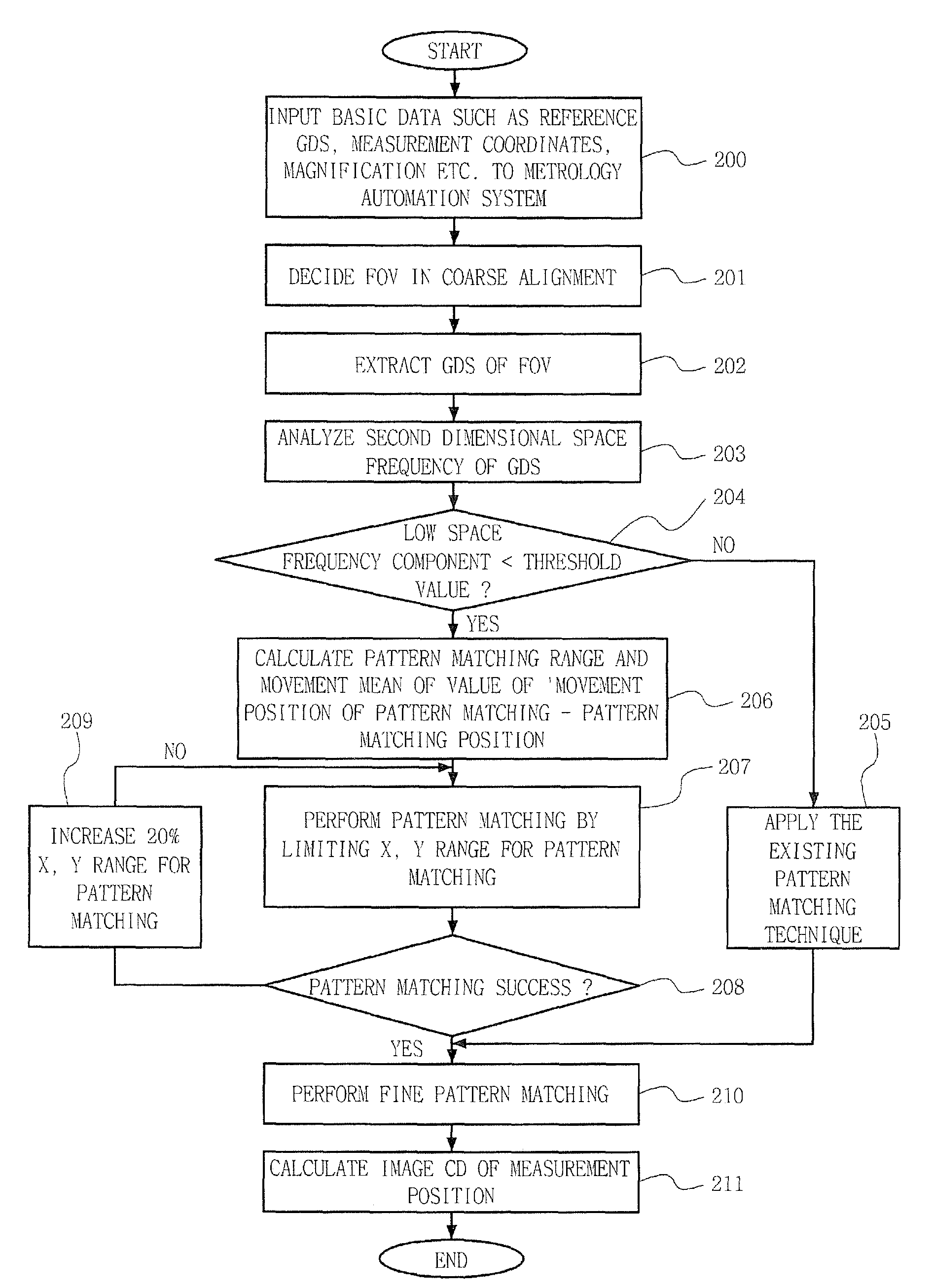
[0025]Accordingly, some embodiments of the invention provide a pattern matching method for use in manufacturing semiconductor memory devices, capable of substantially increasing the success ratio of pattern matching between a GDS image and a CDSEM image. Time required for pattern matching between a GDS image and a CDSEM image can be substantially reduced, thereby increasing a driving rate of a metrology system. In addition, an image shift limitation condition for pattern matching is automatically calculated by analyzing a spatial frequency component of a target pattern, thereby increasing a success rate of position matching of a pattern.
[0030]The method may beneficially further comprise re-performing a pattern matching of the SEM image with the GDS image by increasing 20% the X, Y range for the pattern matching when the pattern matching was not successful in the performing of the pattern matching.
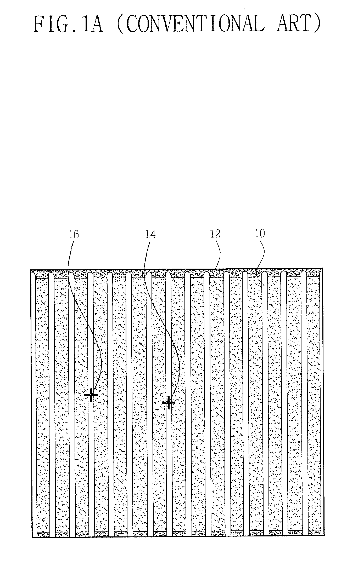
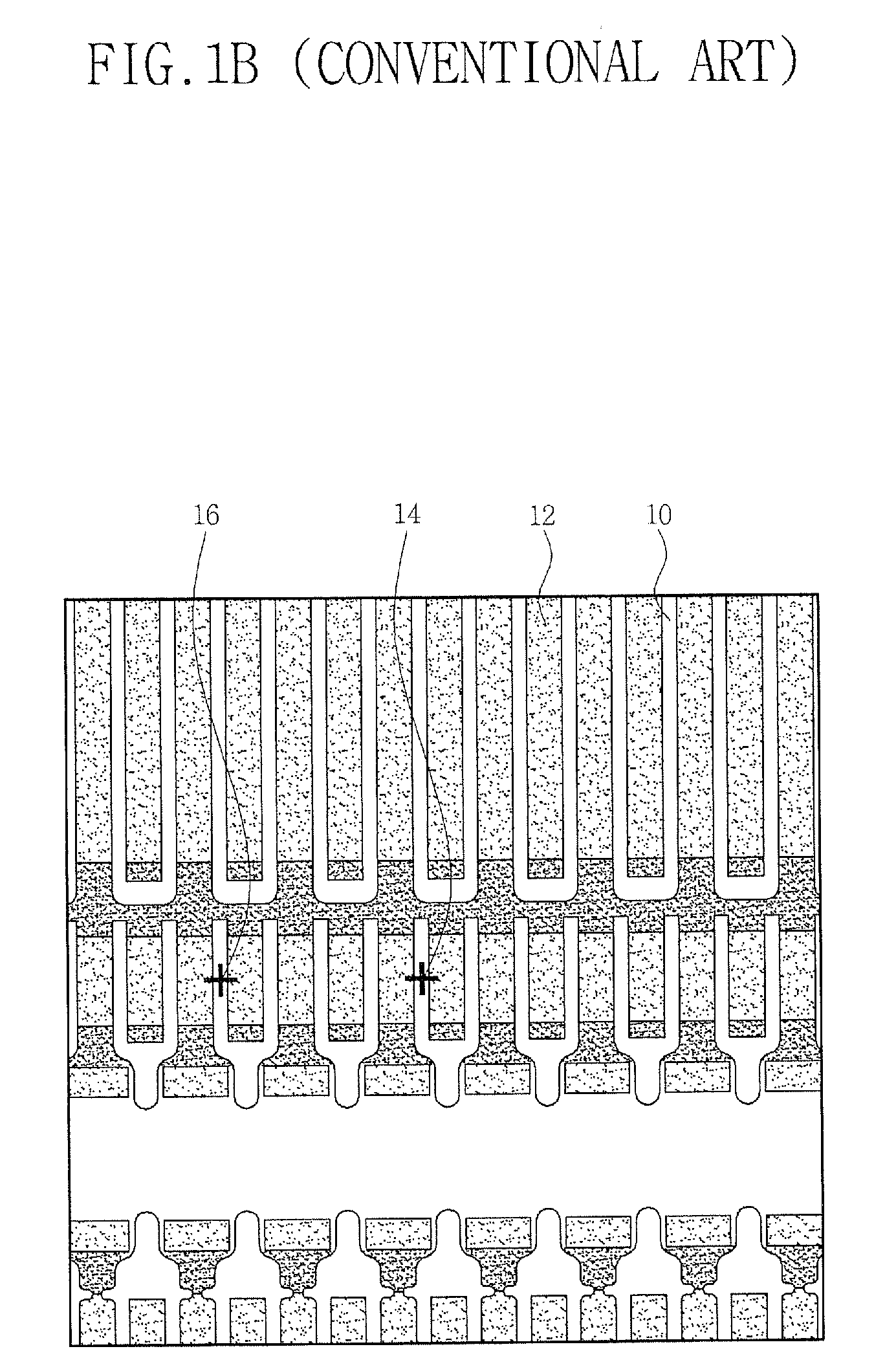
[0031]As described above, in the pattern matching between the GDS image and the SEM image, an SEM image and GDS image corresponding to a specific FOV area are separately extracted, and then it is decided whether the GDS image is a repeated pattern image or non-repeated pattern image. When the GDS image is the repeated pattern image, the range of X and Y directions is limited in performing the pattern matching, thereby dominantly improving a pattern matching rate and substantially reducing a matching fail.
[0032]That is, the pattern matching rate in a global matching can be improved and thus a precise CD measurement value can be obtained, thereby enhancing the reliability and productivity of semiconductor memory devices.
[0033]Further, a large number of measurement points do not have to be reviewed through an improved pattern recognition and matching rate and so a re-measurement is unnecessary, thereby reducing time taken for pattern matching and increasing a driving rate of a metrology system.

Problems solved by technology

In manufacturing semiconductor memory devices by using such several unit processes, step coverage of the material layer may become defective due to step coverage with adjacent patterns, and the resolution level may decrease in a photolithography process and, thus, it may be difficult to obtain a precise profile.
Furthermore, owing to the lack of a process margin, a misalignment may be caused and the reliability of semiconductor memory devices may decrease, thereby negatively affecting yield.
For example, in an SRAM, power consumption is less as compared with other memories, but the speed is very fast, thus the SRAM is widely used as cache memories etc. of large capacity and high performance computers, but six transistors constitute one cell structure and thus there is a disadvantage in view of the integration as compared with other memories.
However a matching rate between patterns reaches only 90% due to an incompletion of matching algorithm between a GDS image and an image from the CDSEM, thus a point that matching fail has occurred is compensated through a correction of recipe.
Like that, for example, when a global matching between GDS image and CD SEM image is not normally performed, a measurement fail occurs and so a CD value of undesired position is measured, thus the reliability of a measurement value falls, causing a failure in a process monitoring step using such a measurement value.
Further, when the global matching between the GDS image and the CDSEM image is not normally performed, there is an inconvenience to have to review a number of measurement points and to have to re-measure relating to a matching fail point, thus causing time consumption and a decrease in a driving rate of metrology system.
However, when a global matching between a GDS design in a FOV and a CDSEM image for an actual pattern is not precise, an alignment of patterns formed in a subsequent process is getting worse, thus largely decreasing reliability and productivity of semiconductor memory devices.

Method used


Image

  • Pattern matching method in manufacturing semiconductor memory devices
  • Pattern matching method in manufacturing semiconductor memory devices
  • Pattern matching method in manufacturing semiconductor memory devices

Examples


Embodiment Construction

[0046]Embodiments of the present invention now will be described more fully hereinafter with reference to FIGS. 3 to 7, in which embodiments of the invention are shown. This invention may, however, be embodied in many different forms and should not be construed as limited to the embodiments set forth herein. Rather these embodiments are provided so that this disclosure will be thorough and complete, and will fully convey the scope of the invention to those skilled in the art.

[0047]Unless otherwise defined, all terms (including technical and scientific terms) used herein have the same meaning as commonly understood by one of ordinary skill in the art to which this invention belongs. It will be further understood that terms used herein should be interpreted as having a meaning that is consistent with their meaning in the context of this specification and the relevant art and will not be interpreted in an idealized or overly formal sense unless expressly so defined herein.

[0048]The num...


PUM


Abstract

A pattern matching method for use in manufacturing a semiconductor memory device increases a pattern matching rate between a GDS image and an SEM image. The pattern matching method includes extracting a scanning electron microscope (SEM) image and a graphic data system (GDS) image to perform a pattern matching; performing a two-dimensional Fourier transform (FFT) for the extracted GDS image and analyzing a low spatial frequency; deciding whether or not a pattern is a repeated pattern or non-repeated pattern by using the analyzed low spatial frequency; and limiting an X / Y range for a pattern matching when the decision result is for the repeated pattern, and then performing the pattern matching between the SEM image and the GDS image.

Description

REFERENCE TO PRIORITY APPLICATION[0001]This application claims priority from Korean Patent Application No. 10-2007-0105341, filed Oct. 19, 2007, the disclosure of which is hereby incorporated herein by reference.FIELD OF THE INVENTION[0002]The present invention relates generally to semiconductor memory devices and, more particularly, to semiconductor memory device manufacturing.BACKGROUND OF THE INVENTION[0003]In general, semiconductor memory devices are manufactured by depositing thin films for several functions on a wafer surface, patterning it, and forming the geometrical structure of various circuits. Unit processes to manufacture such semiconductor devices may be largely classified as several unit processes, such as: wafer and chamber cleaning processes, etc. to eliminate impurity, including an impurity ion implantation process of implanting impurity ions of group 3B, i.e., B, or group 5B, i.e., P or As, into the interior of semiconductor; a thin film deposition process of form...

Claims


Application Information

Patent Timeline
Patent Type & Authority Patents(United States)
IPC IPC(8): G06K9/00G06K9/36G06K9/32
CPCG03F1/84
Inventor HYON, CHAN-KYEONGKANG, YOUNG-SEOGLEE, SANG-HOLEE, HYUN-JONG
Owner SAMSUNG ELECTRONICS CO LTD
Why Eureka
Eureka Blog
Learn More