Exhaust valve mechanism for internal combustion engine

a technology of exhaust valve and internal combustion engine, which is applied in the direction of valve details, valve arrangements, valve drives, etc., can solve the problems of unfavorable wear or damage of the valve mechanism, and achieve the effect of increasing the thickness of the oil film

Active Publication Date: 2012-07-31
VOLVO LASTVAGNAR AB
View PDF5 Cites 7 Cited by
  • Summary
  • Abstract
  • Description
  • Claims
  • Application Information

AI Technical Summary

Benefits of technology

[0003]A valve mechanism in accordance with the foregoing is previously disclosed through WO 03 / 031778, for example, which can be utilized in conjunction with a special type of camshaft with exhaust cams with extra lobes to increase the braking effect of the engine. For example, it is possible to use a higher valve lift height, which gives a more effective gas exchange in the cylinder under engine braking. Such a valve mechanism can also take up greater forces, which means that a higher differential pressure can be permitted over the exhaust valve, which permits a significant increase in the braking effect.
[0007]Undesired movement in the secondary rocker arm during normal engine function is avoided by means of the invention. It is also possible to increase the oil film thickness at the bearing point of the secondary rocker arm by simple means.BRIEF

Problems solved by technology

This angular interval, which is circa 10°, can cause undesired wear or damage to the valve mechanism, when the secondary rocker arm bears against either its cam element or the main rocker arm.
Another problem is that the secondary rocker arm is subjected to unilateral loading under active engine braking, which reduces the thickness of the oil film at its bearing point, which can also lead to wear.

Method used


Image

  • Exhaust valve mechanism for internal combustion engine
  • Exhaust valve mechanism for internal combustion engine
  • Exhaust valve mechanism for internal combustion engine

Examples


Embodiment Construction

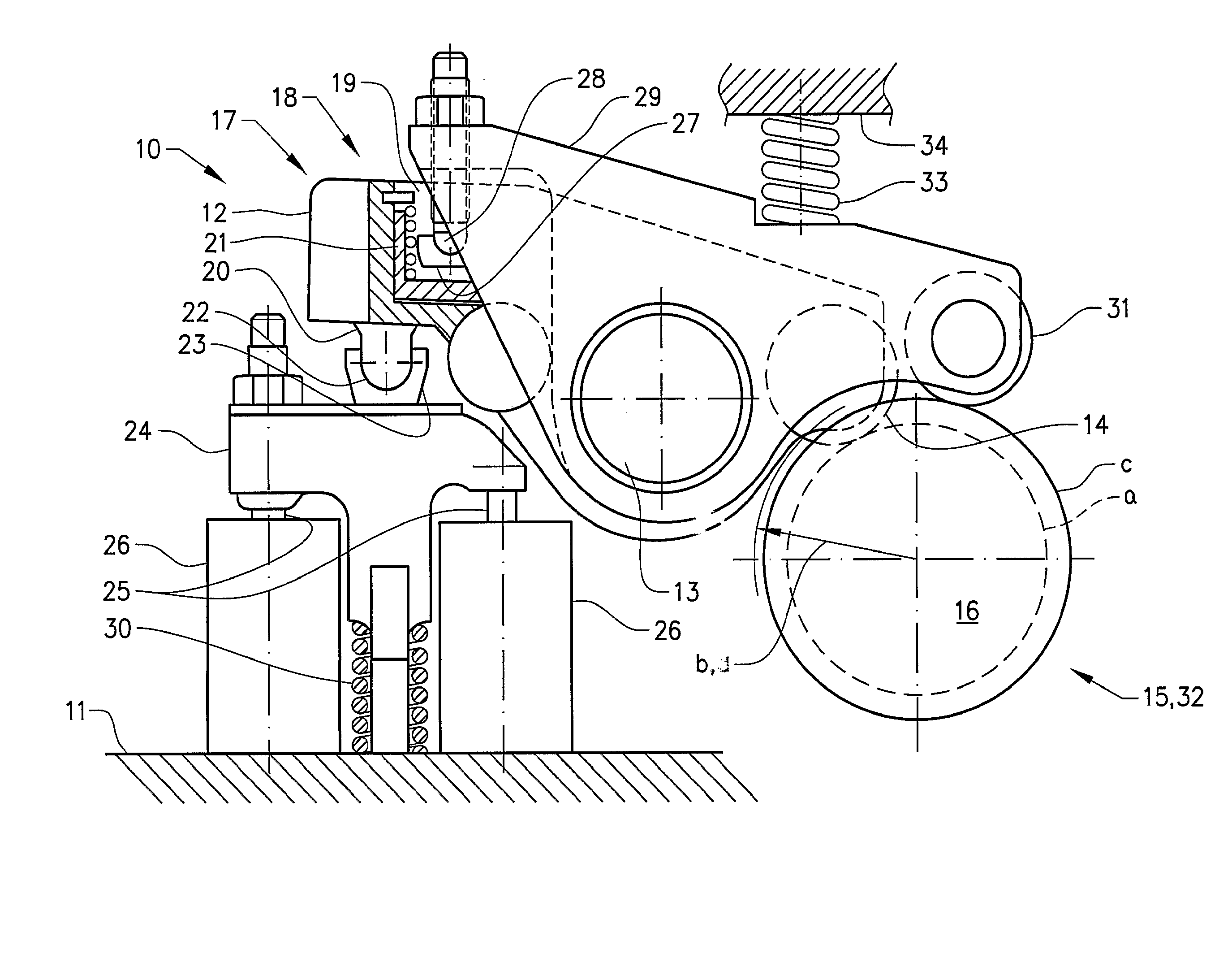
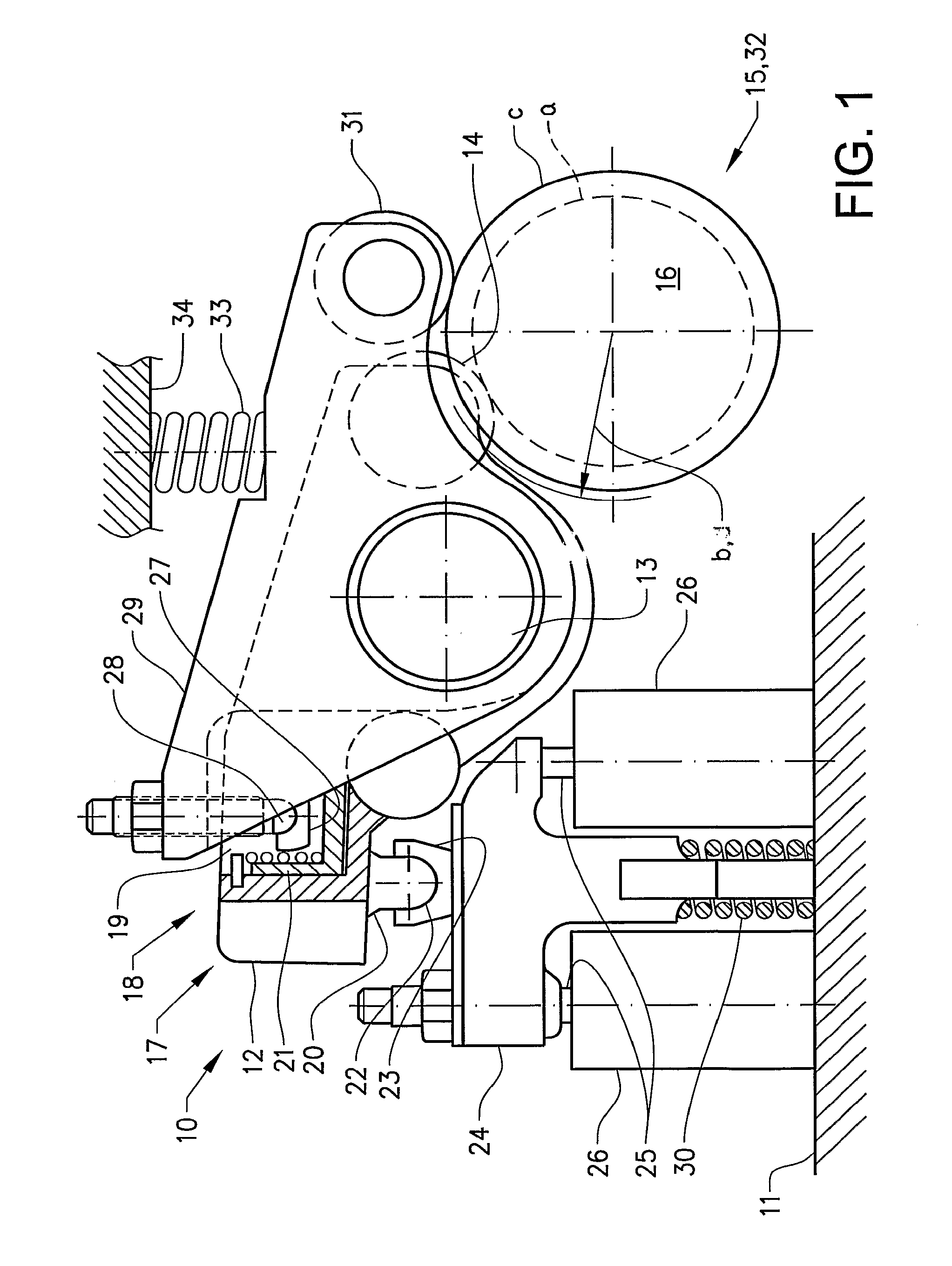
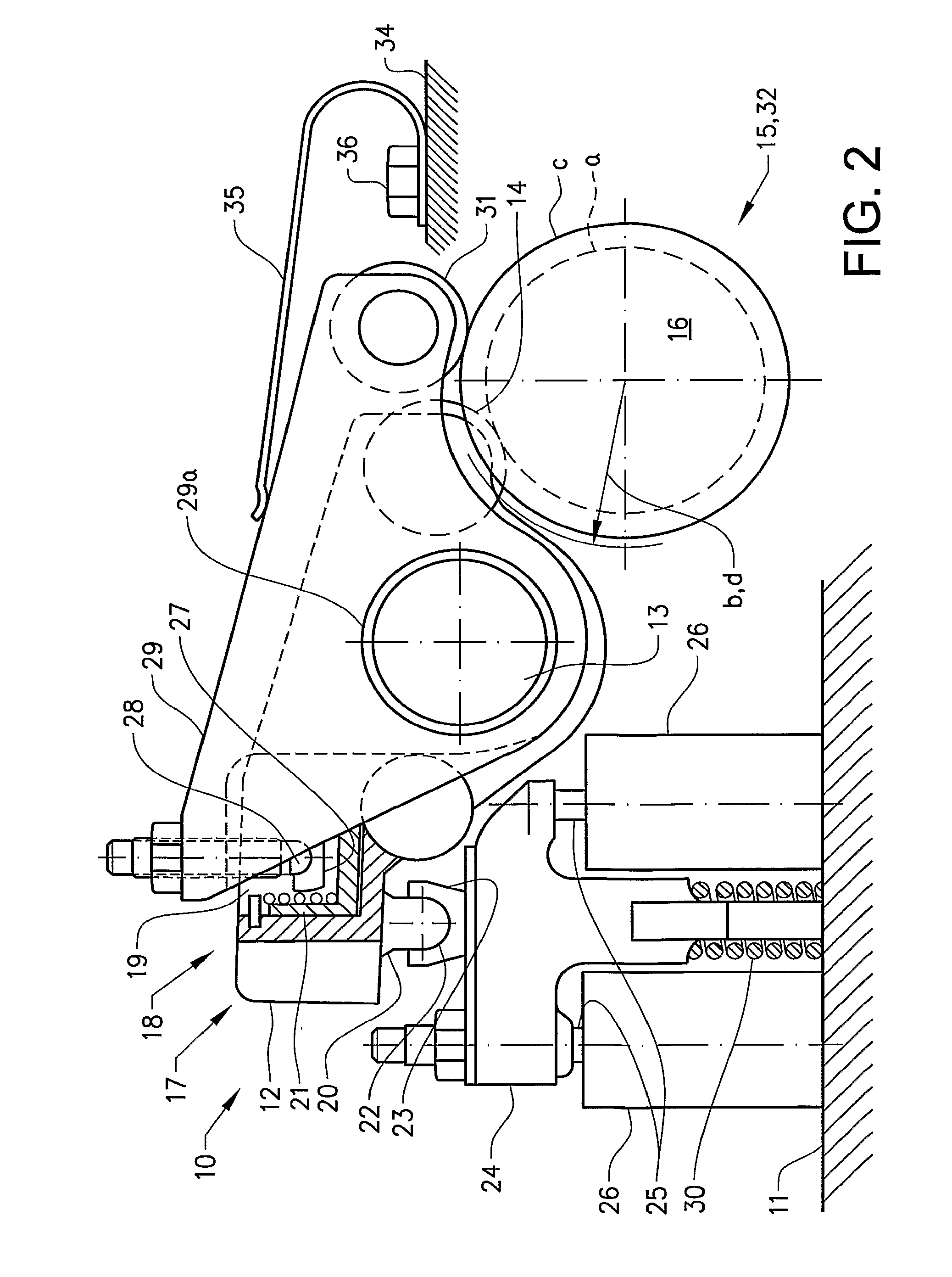
[0011]FIG. 1 illustrates schematically a valve mechanism 10 for the operation of exhaust valves in an internal combustion engine 11. The mechanism 10 corresponds to the mechanism that is illustrated in WO 03 / 031778, FIGS. 2-4, and comprises a main rocker arm 12, which is mounted in such a way as to be capable of rocking on a rocker arm shaft 13. A cam follower roller 14 is rotatably mounted at one end of the main rocker arm 12. The cam follower roller 14 engages with a schematically illustrated cam element 15 on the camshaft 16. The base circle of the cam element 15 is designated with “a”, and its top radius is designated with “b”. At its end 17, which is opposite the end with the cam follower roller 14, the main rocker arm 12 is executed with a double-acting piston cylinder arrangement 18 consisting of two cylinder spaces 19 (of which one is shown vertically sectioned), formed at the end 17 of the rocker arm, with respective pistons 20,21 that are accommodated in the cylinder space...


PUM


Abstract

An exhaust valve mechanism for an internal combustion engine with at least one exhaust valve in every engine cylinder includes a main rocker arm mounted on a rocker arm shaft and a secondary rocker arm arranged on the main rocker arm and mounted on the rocker arm shaft for the activation of an exhaust brake function. A spring device is so arranged as to act between a fixed point on the engine and the secondary rocker arm, in such a way that the latter rocker arm is caused by the spring force to engage with the cam element of the camshaft.

Description

BACKGROUND AND SUMMARY[0001]The present application is a continuation of International Application No. PCT / SE2005 / 000179, filed Feb. 9, 2005, which claims priority to SE 0400453-7, filed Aug. 23, 2004, both of which are incorporated by reference.[0002]The present invention relates to an exhaust valve mechanism for an internal combustion engine with at least one exhaust valve in each engine cylinder, which mechanism comprises a main rocker arm for each cylinder mounted on the rocker arm shaft for normal operation of the exhaust valve by the actuation of a camshaft with a cam element for each rocker arm and a secondary rocker arm arranged on the main rocker arm and mounted on a rocker arm shaft, for the activation of an exhaust brake function, which activation is achieved through the supply of hydraulic pressure to a piston cylinder which acts between both the rocker arms and takes place through the effect of one of the cam elements of the camshaft.[0003]A valve mechanism in accordanc...

Claims


Application Information

Patent Timeline
Patent Type & Authority Patents(United States)
IPC IPC(8): F01L1/34F01L1/18F01L13/06F02D13/04
CPCF01L1/181F01L13/065F01L1/267F01L2001/186F01L2105/00F02D13/04F01L2001/467F01L2305/00
Inventor PERSSON, PERBONDESON, HANSNOBELIUS, ANDERSGRANKVIST, JOHAN
Owner VOLVO LASTVAGNAR AB
Why Eureka
Try Eureka