Supercharge Your Innovation With Domain-Expert AI Agents!

Combustion deposition burner and/or related methods

a burner and combustion technology, applied in the direction of combustion types, plasma techniques, lighting and heating apparatuses, etc., can solve the problems of application not knowing of any commercially available burners, limited control mechanisms, and limited deposition of optical preforms

Inactive Publication Date: 2012-07-31
GUARDIAN GLASS LLC
View PDF23 Cites 3 Cited by
  • Summary
  • Abstract
  • Description
  • Claims
  • Application Information

AI Technical Summary

Benefits of technology

The patent text describes a new technique for coating glass and other substrates using a combustion chemical vapor deposition (CCVD) process. This process involves using a linear burner to deliver precursors to the flame, where they react to form the coating. The inventor has developed a burner design that enhances control over precursor delivery, allowing for greater reaction control. The technique also allows for independent control over precursor reaction zones, resulting in more consistent products. The patent text also describes the use of the technique to deposit anti-reflective films on glass substrates to improve optical properties. The technical effects of this patent text include improved control over coating growth, greater reaction control, and more consistent product quality.

Problems solved by technology

Unfortunately, however, these control mechanisms can be fairly limited, depending on the particular application.
However, these products appear to involve substantially different burner designs and also appear to be limited to the deposition of optical preforms.
Indeed, the inventor of the instant application is not aware of any commercially available burners that have been developed specifically for combustion deposition techniques.

Method used


Image

  • Combustion deposition burner and/or related methods
  • Combustion deposition burner and/or related methods
  • Combustion deposition burner and/or related methods

Examples


Embodiment Construction

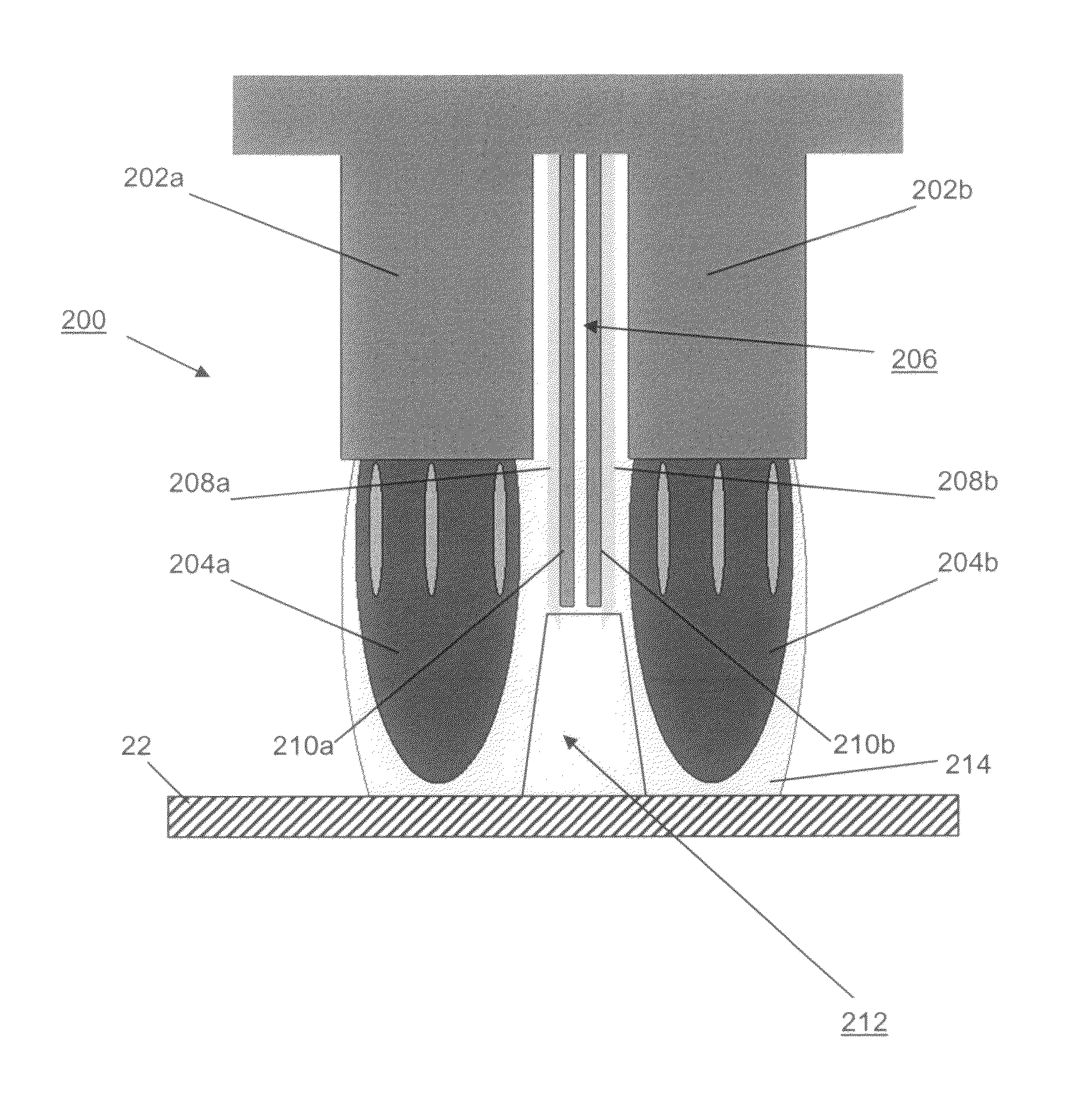
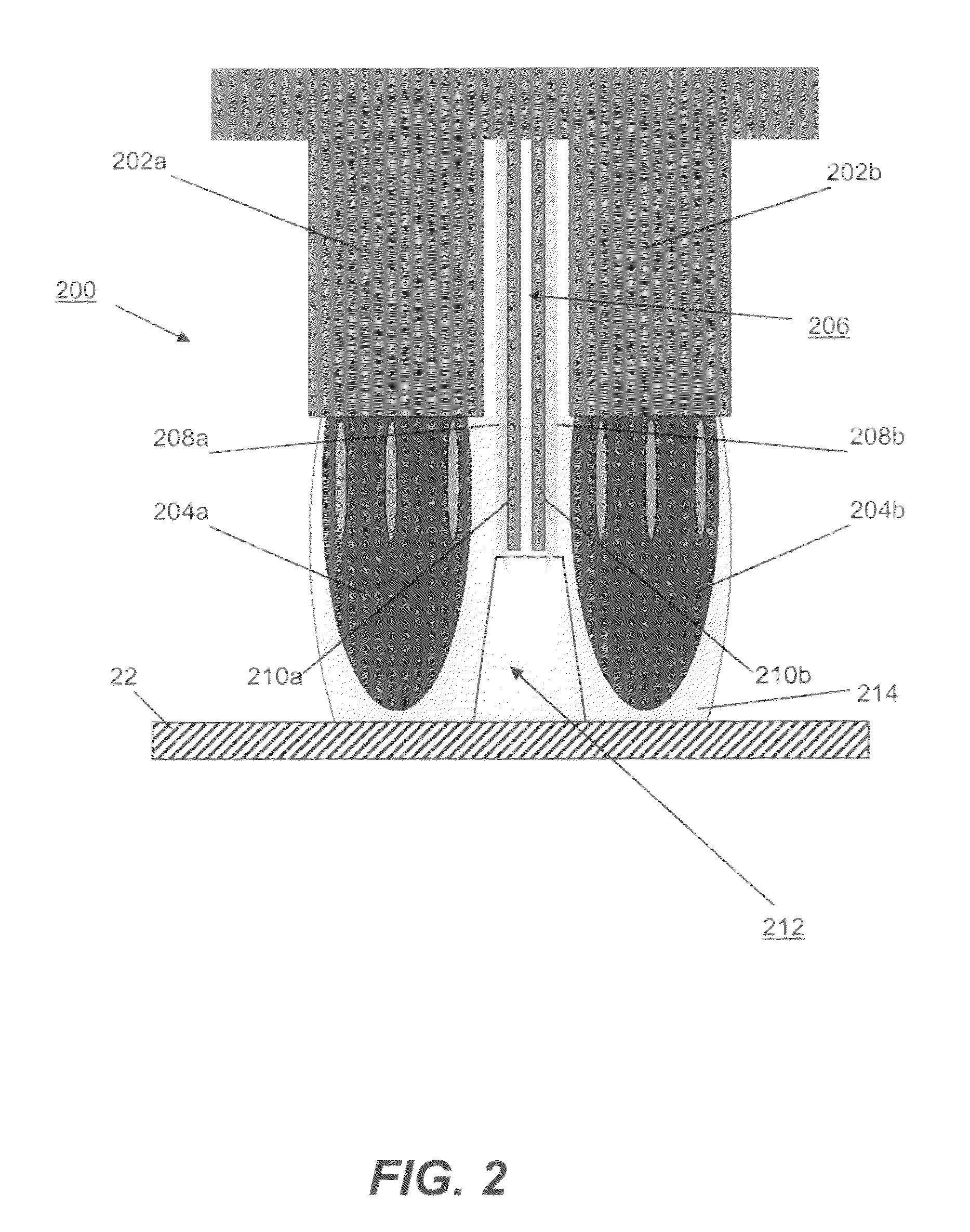
[0026]Certain example embodiments relate to an improved burner for combustion deposition depositing coatings that enables enhanced control of reaction conditions and thus coating properties. In certain example instances, the burners of certain example embodiments may be used to combustion deposition deposit metal oxide films (e.g., silicon oxide, titanium oxide, and / or other metal oxides) on substrates. Advantageously, the burner design of certain example embodiments allows precursor material to be delivered to a specific location within the flame. In certain example embodiments, a precursor may be delivered substantially directly within the precursor reaction zone, and the burner design of certain example embodiments may help to reduce the occurrence of precursor pre-reactions along the delivery path (e.g., upstream of the precursor reaction zone). Furthermore, in certain example embodiments, the reaction location and / or reaction window may be changed so as to affect chemical react...


PUM

PropertyMeasurementUnit
distanceaaaaaaaaaa
wavelengthsaaaaaaaaaa

Abstract

Certain example embodiments relate to a burner for use in combustion deposition depositing a coating on a substrate. First and second spaced-apart combustion gas manifolds are configured to respectively produce first and second flames (which may effectively combine to form a single flame front beyond the outer face of the burner in certain example embodiments). The first and second combustion gas manifolds form a precursor reaction zone therebetween. An adjustable precursor delivery manifold located between the first and second combustion gas manifolds is configured to receive a precursor used in forming the coating. The precursor delivery manifold is positioned so as to substantially directly provide the precursor to a desired or predetermined portion of the precursor reaction zone. The precursor delivery manifold includes first and second cooled walls arranged to reduce the occurrence of precursor pre-reactions upstream of the precursor reaction zone. The burners of certain example embodiments may be used to combustion deposition deposit metal oxide coatings onto glass substrates.

Description

FIELD OF THE INVENTION[0001]Certain example embodiments of this invention relate to the deposition of metal oxide coatings onto substrates via combustion deposition. More particularly, certain example embodiments relate to a burner design that enables a precursor to be delivered substantially directly within a desired portion of a precursor reaction zone, while also helping to reduce the occurrence of precursor pre-reactions along the precursor delivery path (e.g., upstream of the precursor reaction zone). In certain example embodiments, the reaction location and / or reaction window may be changed so as to affect chemical reactions, adjust coating properties, enhance uniformity, control dynamic deposition rate, etc.BACKGROUND AND SUMMARY OF EXAMPLE EMBODIMENTS OF THE INVENTION[0002]Reagent concentration, temperature, and residence time are known factors that drive chemical reactions. Combustion chemical vapor deposition (combustion CVD) processes are no different. The significance of...

Claims


Application Information

Patent Timeline
Patent Type & Authority Patents(United States)
IPC IPC(8): C23C16/00C23C16/455C23C16/453
CPCC03C17/002C23C16/402C23C16/453F23D14/08F23D14/78F23D23/00F23D99/003F23D91/02
Inventor MCLEAN, DAVID D.
Owner GUARDIAN GLASS LLC
Features
  • R&D
  • Intellectual Property
  • Life Sciences
  • Materials
  • Tech Scout
  • Unparalleled Data Quality
  • Higher Quality Content
  • 60% Fewer Hallucinations
Learn More