Adjustable lens system for real-time applications

a lens system and real-time application technology, applied in the field of lenses, can solve the problems of unsuitable the fluid refractive interface taking uncontrollable shapes, and the general inability to record real-time images or video sequences, and address the problem of real-time recording of images through optical devices

Inactive Publication Date: 2012-07-31
KONINK PHILIPS ELECTRONICS NV
View PDF8 Cites 13 Cited by
  • Summary
  • Abstract
  • Description
  • Claims
  • Application Information

AI Technical Summary

Benefits of technology

[0012]The lens system according to the first aspect is advantageous since it allows recording of high speed images during adjustment of the refraction, e.g. adjustment of focal point or deflection, since the voltage rate is limited such that the refraction changes continuously, preferably both with respect to temporal change and with respect to a spatial change of the interface, i.e. the interface preferably changes its shape in a controlled manner from the first refraction to the second refraction. Thus, all the time during adjustment, the interface takes intermediate shapes that allows high quality imaging during the entire refraction adjustment from the first refraction to the second refraction.
[0013]Thus, real-time ultrasonic imaging and real-time ultrasonic ablation can be performed with such lens system utilizing the effect that the lens has a controlled shape during the adjustment procedure and therefore does not suffer from reduced performance during adjustment. Thus, there is no need to stop using the lens during focal point adjustment or the like. This can save time for many applications, such as medical applications where it becomes possible to perform quicker diagnostic ultrasonic imaging examinations, or to perform quicker treatments in case the lens system is used for focusing ultrasonic ablation beams.
[0015]Depending on the actual materials, dimensions and other design parameters, the skilled person will know how to select a limited rate of voltage change to avoid oscillation of the interface, e.g. by performing a test to observe the behavior of the interface during different rate of voltage changes. This may be done by recording high speed images and observing focus performance of the lens system during the refraction adjustment at different rate of voltage changes. Based on these results the highest rate of voltage change can be chosen that results in a stable focus performance during the change. Further, it is possible: 1) to measure capacitance changes of the lens, 2) to use an interferometer to look at meniscus, and 3) to image through the lens during adjustment, i.e. when the interface is moving, and see when the image becomes blurred.
[0040]Thus, such medical treatment device utilizes the advantageous effect of the lens system of the first aspect, namely the possibility of using e.g. ultrasonic pulses at high speed during adjustment of e.g. a focal point, hereby allowing ablation along a pre-defined trajectory.

Problems solved by technology

However, it is a well known problem with fluid type lenses, that rapid adjustment of the lens will cause the fluids to oscillate, thereby causing the refractive interface between the fluids to take uncontrollable shapes during the adjustment until the oscillations die out and the interface has changed to another stable shape.
This means that real-time high quality imaging through such lens during the adjustment will be heavily blurred or distorted, and thus such lenses are in general not suited for recording of real-time images or video sequences.
The same problems occurs for medical treatment applications of such lenses where precise control e.g. of ultrasonic ablation waves radiated towards living tissue is crucial.
However, still WO 2006 / 030328 A1 does not address the issue of real-time recording of images through the optical device.

Method used


Image

  • Adjustable lens system for real-time applications
  • Adjustable lens system for real-time applications
  • Adjustable lens system for real-time applications

Examples


Embodiment Construction

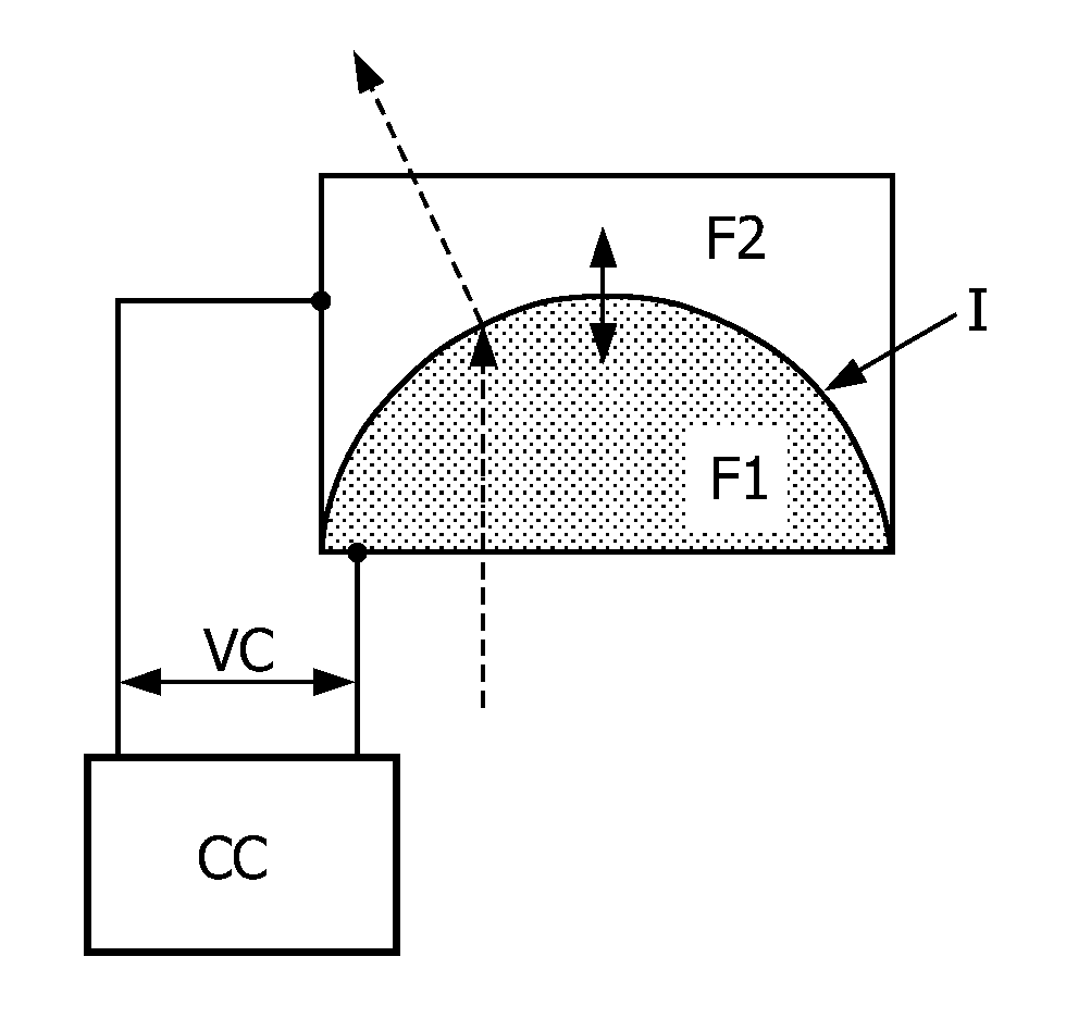
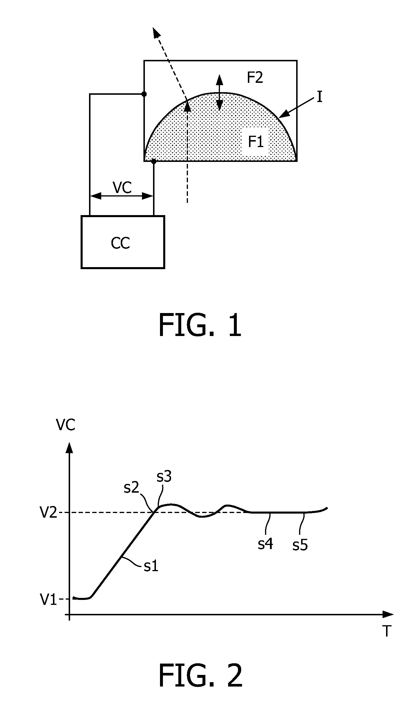
[0050]FIG. 1 illustrates a sketch of a lens system embodiment where a first fluid F1 and a second fluid F2 are arranged in direct contact at an interface I, in other words a fluid lens. One fluid should be conductive while the other fluid should be insulating. In the illustrated embodiment, the fluids F1, F2 are arranged in a container such that the interface I has a shape which is rotational symmetric around an axis, namely such that the fluids F1, F2 are arranged in a meniscus shape, with the interface I having a spherical shape. The double-arrow indicates possible movement of the interface I which allows adjustment of the refraction of incoming waves (one ray is illustrates by the dashed arrow). A control circuit CC applies a voltage VC to the lens via electrodes (not expressly illustrated). A first electrode is in contact with the electrically conductive fluid while a second electrode is behind an isolating layer covering the inner wall(s) of the lens. Thus, the lens utilizes th...


PUM


Abstract

An adjustable fluid type lens system is provided that allows e.g. ultrasound imaging through the lens during adjustment of the lens. The lens includes a container enclosing two immiscible fluids, e.g. water and oil, being in contact with each other at an interface. Incoming waves are then refracted at this interface. The shape of the interface, and thereby the refraction property, is adjustable by adjusting a voltage applied to the lens. The two fluids are selected such that they together exhibit a mechanical damping which is critical or near critical. A control circuit generates the electric voltage for adjusting the refraction from one value to another, the control circuit being arranged to change the electric voltage such that a rate of voltage change is limited to avoid oscillation of the interface, thereby adjusting refraction of incoming waves at the interface in a continuous manner. This makes it possible to use the lens while it is during adjustment from one refraction value to another, since the interface shape will at all time during the adjustment have a controlled shape. The voltage can be either a continuous voltage or a discrete stepwise (digital) voltage which is just controlled with respect to step size and temporal extension of the steps. The lens system has a number of applications e.g. within the medical field, e.g. for ‘on the fly’ high speed ultrasound imaging, or for ultrasound ablation applications where ablation can be performed during adjustment of the lens to follow a pre-defined trajectory.

Description

CROSS REFERENCE TO RELATED CASES[0001]Applicants claim the benefit of International Application Number PCT / IB2008 / 055205, filed Dec. 10, 2008, and Provisional Application Ser. No. 61 / 013,836, filed Dec. 14, 2007.FIELD OF THE INVENTION[0002]The invention relates to the field of lens systems, more specifically the invention relates to the field of adjustable lens systems based on refraction at an interface between two fluids.BACKGROUND OF THE INVENTION[0003]Adjustable lens systems for medical imaging or treatment applications are known, e.g. lens systems arranged for adjusting refraction of ultrasound. So-called fluid lenses or liquid lenses as described in WO 2003 / 069380 by Philips can be used for such applications. In essence, fluid lens technology allows light, or other rays or waves, to be refracted through alterations in physical boundaries of a fluid filled cavity with specific refractive indices. This process is known as electro-wetting, whereby the fluid within the cavity is m...

Claims


Application Information

Patent Timeline
Patent Type & Authority Patents(United States)
IPC IPC(8): G02B1/06G02B3/12
CPCG02B3/14
Inventor SUIJVER, JAN FREDERIKHALL, CHRISTOPHER STEPHENFERNANDEZ, ANNA TERESAKUIPER, STEINSHI, YAN
Owner KONINK PHILIPS ELECTRONICS NV
Why Eureka
Try Eureka