Motor

a motor and motor body technology, applied in the field of motors, can solve the problems of large electricity consumption, inability to reduce the entire size, so as to reduce the size, save electricity consumption, and reduce the cost

Inactive Publication Date: 2012-08-14
LIN YU MING
View PDF10 Cites 16 Cited by
  • Summary
  • Abstract
  • Description
  • Claims
  • Application Information

AI Technical Summary

Benefits of technology

[0010]Accordingly, the primary object of the present invention is to provide a motor, wherein the metallic casings of a conventional motor are omitted and this new motor is assembled by wrapping the copper wires mechanically that in addition to a reduced size and lower costs, electricity consumption can be saved and performance of the motor can be improved.
[0011]Another object of the present invention is to provide a motor, wherein bearings are directly enclosed in insulation end plates to isolate from dusts in ambient environment that in addition to lowering noise, a service life of the motor can be even extended.
[0012]Still another object of the present invention is to provide a motor, wherein copper wires on a coil of an inner stator are electrically connected with a power cord by plugging; therefore, time and labor work can be saved in the manufacturing process.

Problems solved by technology

The conventional motor is provided with several shortcomings, as listed below:1. The copper wires A must be transfixed and formed manually; therefore, manpower and materials are wasted.2. A height of the motor cannot be reduced and its entire size cannot be diminished; therefore, when operating, the motor is not very stable and consumes a lot of electricity.
In addition, noise is loud, efficiency cannot be improved and packing and transportation costs cannot be reduced.3. As the bearings 400 at the upper and lower ends of the motor rotor 300 must be enclosed by the metallic casings 500 at the upper and lower ends, the costs cannot be reduced.4. To form after the copper wires A have been fastened, the varnish has to be used; therefore, the conventional motor is not environmentally friendly.5. When the copper wires A are electrically connected with a power cord (not shown in the drawing), a Polyamide insulator has to be peeled off, which wastes labor work and time in the manufacturing process.

Method used


Image

  • Motor
  • Motor
  • Motor

Examples


Embodiment Construction

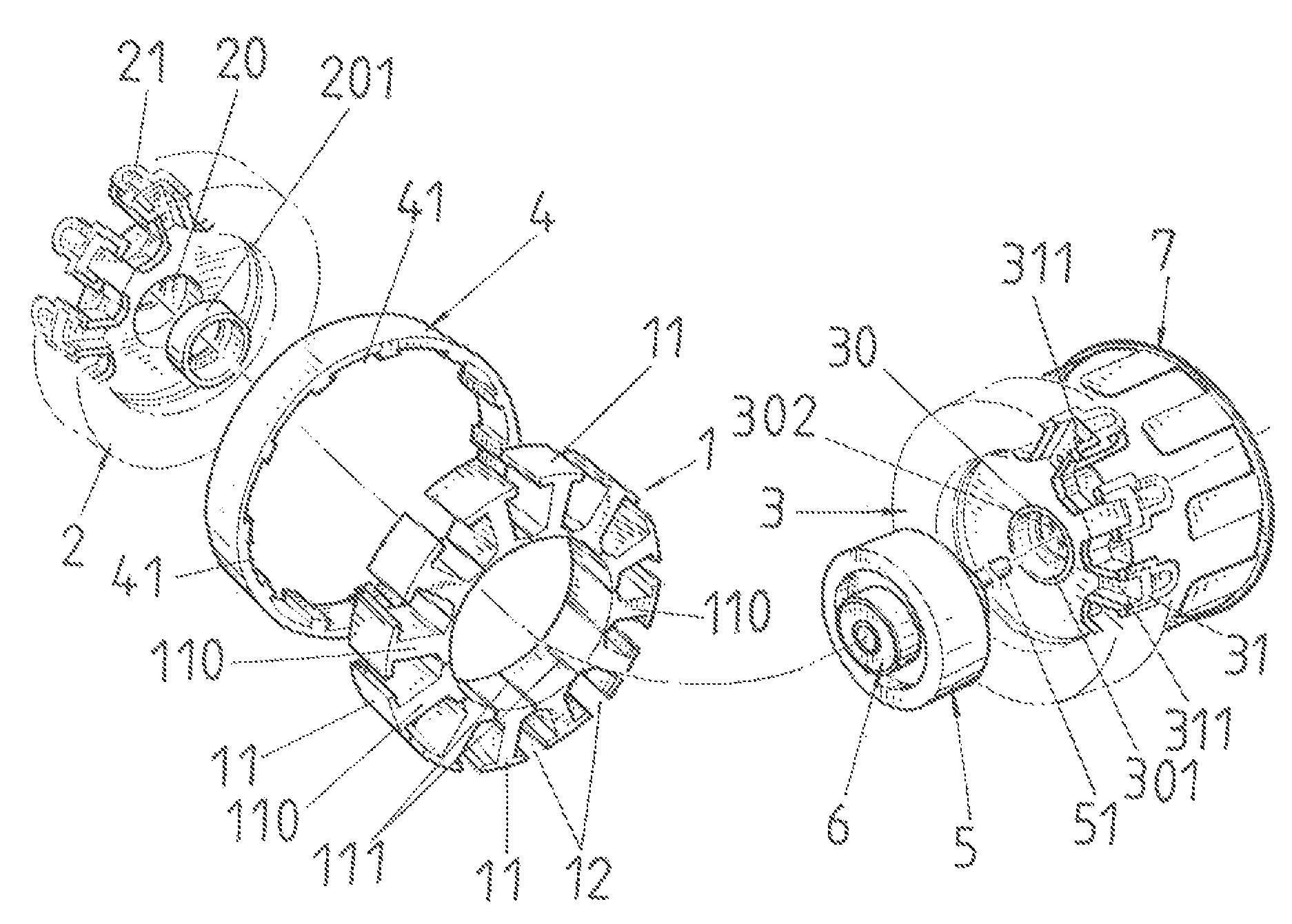
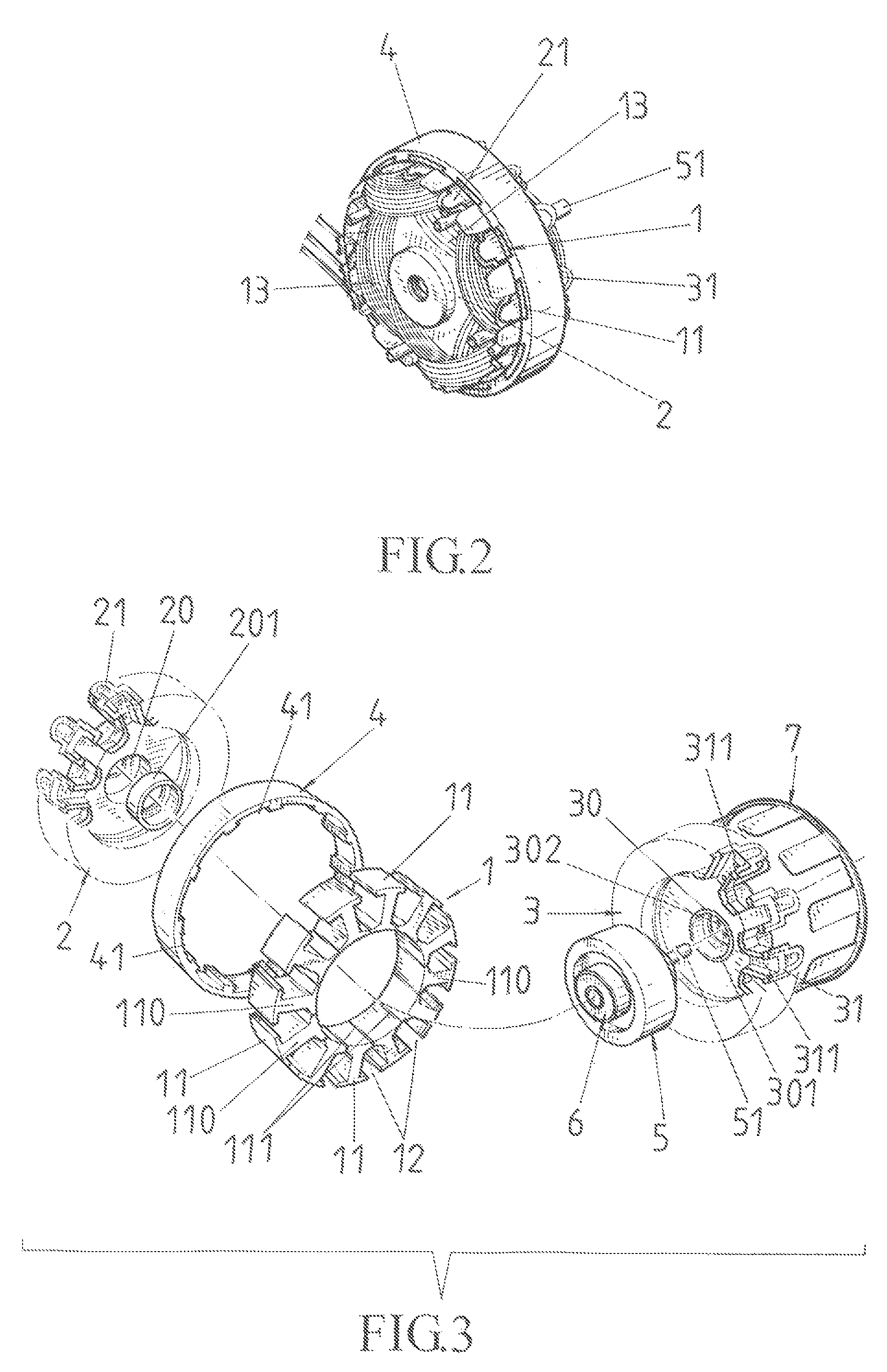
[0022]Referring to FIGS. 2 and 3, the present invention comprises an inner stator 1, two insulation plates 2, 3, an outer frame 4, a rotor 5 and two bearings 6, wherein an outer rim of the annular-shaped inner stator 1 is extended with plural T-shaped blocks 11, with a U-shaped wire slot 12 being formed between two neighboring T-shaped blocks 11. The wire slots 12 are provided with a coil 13 of a thickness, with the coil 13 being formed by stacking several copper wires through a wire wrapping machine. An exterior ring of the inner stator 1 is sheathed with the outer frame 4, two sides of which are two insulation plates 2, 3 respectively. Plural wedge-shaped latch slots 41 at an inner ring of the outer frame 4 provide for latching the plural T-shaped blocks 11 of the inner stator 1. Two sides of a shaft 51 in a center of the rotor 5 are provided respectively with the bearing 6, circular slots 20, 30 at inner sides in centers of the insulation plates 2, 3 provide respectively for latc...


PUM


Abstract

The present invention discloses a motor. A rotor and bearings are installed first and then copper wires are wrapped by a machine. Therefore, the copper wires wrapped are denser and thinner that a space filling factor is improved and an entire size of the motor is reduced. In addition to saving of electricity consumption and improvement of motor performance, the bearings are directly enclosed in two insulation plates to isolate from ambient environment, so that dust contamination can be reduced and noise from operation can be decreased, thereby extending a service life of the motor. Furthermore, packing and transportation costs can be even saved. Additionally, the insulation plates include plural insertion slots for insertion with copper plates which are electrically connected with a motor power cord. Thus, an inner stator can be connected with the power cord by plugging, so as to save labor work and time.

Description

BACKGROUND OF THE INVENTION[0001]a) Field of the Invention[0002]The present invention relates to a motor and more particularly to a motor which is small in size, has a lower cost and is without much noise that in addition to a saving of electricity consumption and improvement of motor performance, packing and transportation costs can be saved. Furthermore, manpower and time can be saved in a manufacturing process.[0003]b) Description of the Prior Art[0004]Referring to FIG. 1, for a conventional motor, through-holes 101 on an inner stator 100 which is made of a silicon steel sheet are first inserted with grooved insulators 200 which is made of plastic, and an entire bundle of copper wires A is wire-wrapped and then lead in manually, with the copper wires A penetrating into the through-holes 101 of the inner stator 100. A plastic grooved wedge (not shown in the drawing) is latched in next, and the copper wires A are fastened with a rope B and then shaped. Then, the copper wires A are ...

Claims


Application Information

Patent Timeline
Patent Type & Authority Patents(United States)
IPC IPC(8): H02K3/46
CPCH02K1/146H02K3/522
Inventor LIN, YU-MING
Owner LIN YU MING
Why Eureka
Try Eureka