
Elastic wave device and electronic component

a technology of elastic wave and electronic components, applied in the field of elastic wave devices, can solve the problems of not being able to stabilize the resonant frequency, electrodes have no influence on the resonant frequency to be obtained, and it is not possible to completely eliminate the influence of a frequency change in the vibration mod

Inactive Publication Date: 2012-08-14
NIHON DEMPA KOGYO CO LTD
View PDF27 Cites 6 Cited by
  • Summary
  • Abstract
  • Description
  • Claims
  • Application Information

AI Technical Summary

Benefits of technology

The present invention provides an elastic wave device that is small-sized and stable with respect to frequency fluctuations due to aging. The device includes a first propagation mode portion and a trapping energy mode portion, which are both in an elastic wave waveguide. A cutoff portion is provided to prevent the influence of a mass change in the electrodes on the resonant frequency. The elastic wave in the zero-order propagation mode is propagated in the elastic wave waveguide as a first elastic wave, and a second elastic wave in an energy trapping mode is excited by a specific frequency component included in the first elastic wave. This resonance response is obtained without providing an electrode on the trapping energy mode portion, and the change in frequency characteristic due to a mass change in the electrodes does not occur. The elastic wave device is suitable for high-frequency resonance and can be further miniaturized.

Problems solved by technology

However, these elastic wave devices are constituted as what is called a composite resonator (composite vibrator) type elastic wave device to generate resonance by using vibration in the same mode as a vibration mode generated in regions having electrodes provided thereon, so that it is not possible to completely eliminate the influence that a frequency change in the vibration mode due to a mass change in the electrodes has on the resonant frequency to be obtained in the region having no electrode provided thereon.
Accordingly, it is not possible to stabilize the resonant frequency sufficiently in conventional methods disclosed in above-described respective Patent Documents and Non Patent Documents, and the change with time in the electrode mass is still a significant obstacle to a further increase in frequency and miniaturization of the elastic wave device.

Method used


Image

  • Elastic wave device and electronic component
  • Elastic wave device and electronic component
  • Elastic wave device and electronic component

Examples


Embodiment Construction

)

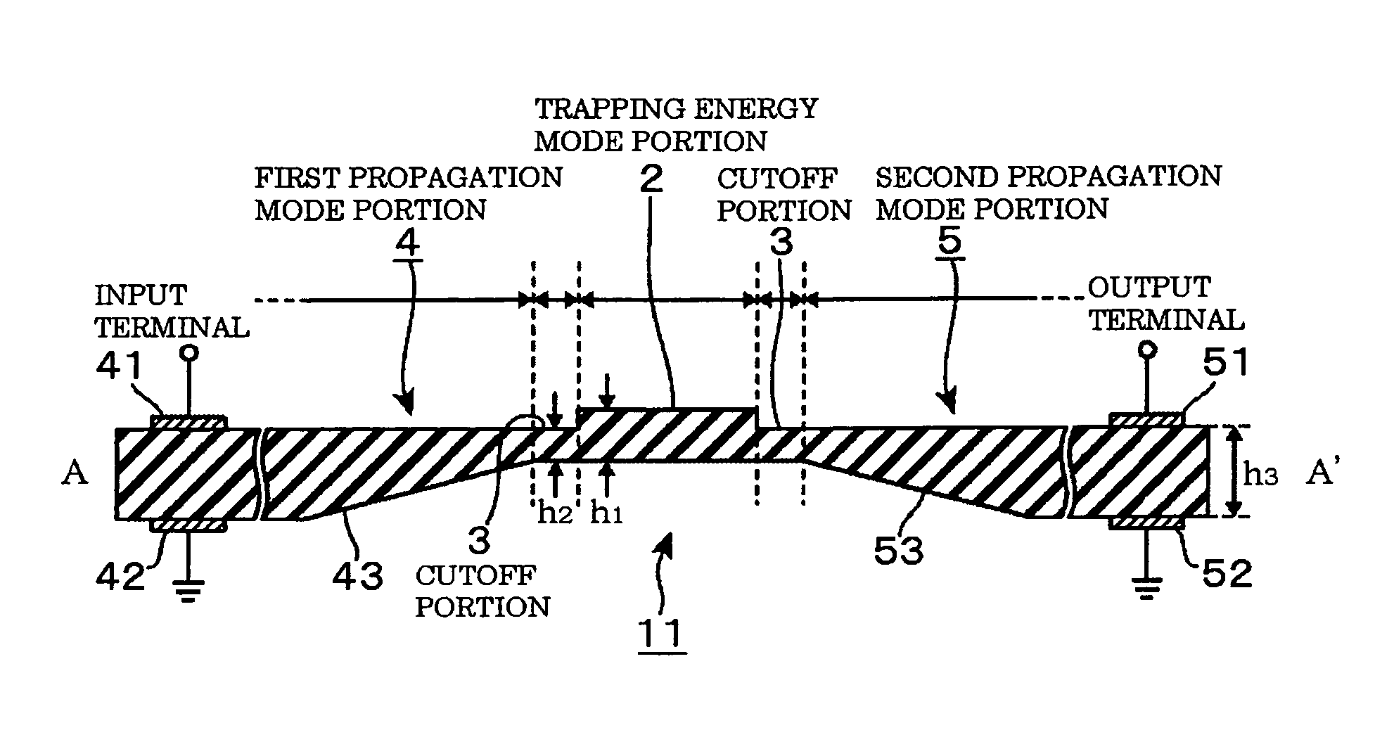
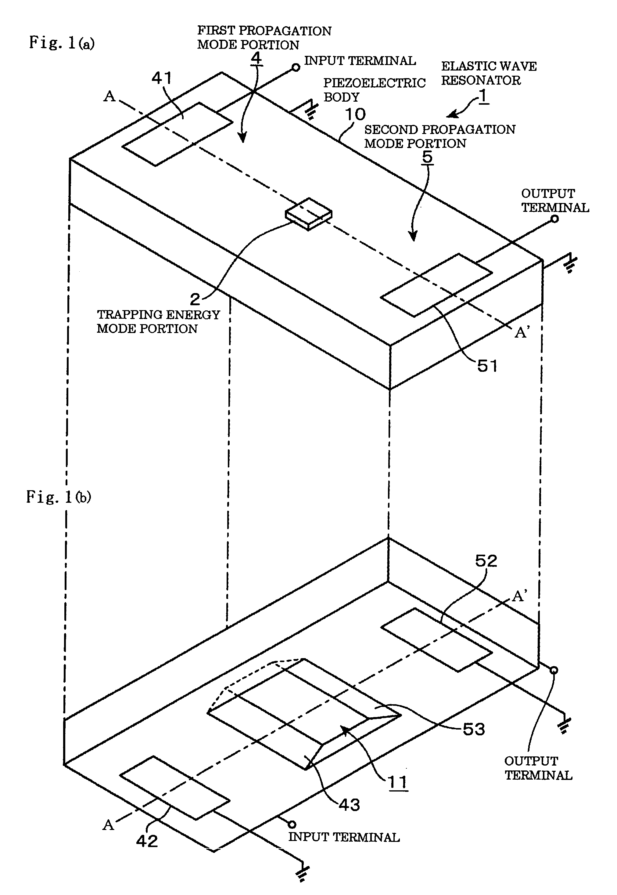
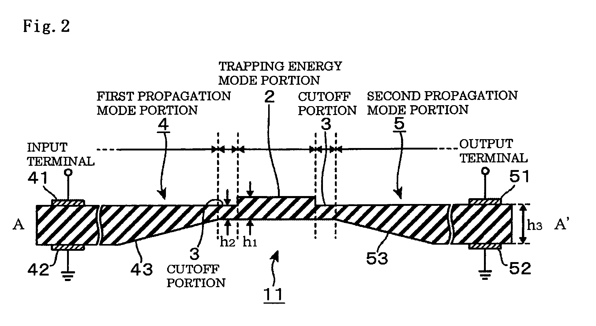
[0050]Hereinafter, a constitution of an elastic wave resonator 1 being one example of an elastic wave device according to an embodiment will be explained with reference to FIG. 1(a), FIG. 1(b), and FIG. 2. As illustrated in perspective views in FIG. 1(a) and FIG. 1(b) and a vertical sectional side view in FIG. 2 (that illustrates a vertical cross section at positions of A-A′ illustrated in FIG. 1(a) and FIG. 1(b)), the elastic wave resonator 1 is constituted in a manner that electrodes 41, 42, 51, and 52 are provided at both ends of a piezoelectric body 10 being an elastic body material, which is processed to a small piece, to be set as an elastic wave waveguide through which elastic waves in propagation modes are propagated, and at, for example, a center portion on the elastic wave waveguide, a trapping energy mode portion 2 to excite an elastic wave in an energy trapping mode is provided. Here, the rectangular shaped electrodes 41, 42, 51, and 52 are illustrated in FIG. 1(a), FIG...


PUM


Abstract

To provide an elastic wave device that is small sized and in which a frequency fluctuation due to a change with time hardly occurs, and an electronic component using the above elastic wave device. A trapping energy mode portion 2 provided in an elastic wave waveguide 10 made of an elastic body material excites a second elastic wave being an elastic wave in an energy trapping mode by a specific frequency component included in a first elastic wave being an elastic wave in a zero-order propagation mode propagated from a first propagation mode portion 4, and a cutoff portion 3 provided in a peripheral region of the trapping energy mode portion 2 has a cutoff frequency being a frequency higher than that of the second elastic wave. A second propagation mode portion mode-converts the second elastic wave leaked through the cutoff portion to a third elastic wave being the elastic wave in the zero-order propagation mode to propagate the third elastic wave.

Description

BACKGROUND OF THE INVENTION[0001]1. Field of the Invention[0002]The present invention relates to an elastic wave device using a trapping energy effect, and particularly relates to a technique to miniaturize the elastic wave device.[0003]2. Description of the Related Art[0004]When controlling frequency or selecting frequency in a small-sized high frequency communication device such as a portable terminal, there is a small-sized high frequency communication device employing an oscillator or a filter using an energy trapping type resonator (hereinafter, the oscillator and the filter are generically called an elastic wave device).[0005]An energy trapping type elastic wave device obtains a necessary frequency response by using resonance to occur by trapping energy of thickness vibration in a piezoelectric body of quartz-crystal or the like. The thickness vibration to be used in the elastic wave device of this type vibrates at a frequency on a high frequency side in the vicinity of a cuto...

Claims


Application Information

Patent Timeline
Patent Type & Authority Patents(United States)
IPC IPC(8): H01L41/08H03H9/19H01L41/09H01L41/18H01L41/22H03H9/56
CPCH03H9/0211H03H9/132H03H9/19H03H9/564H03H9/566
Inventor ONOE, MORIO
Owner NIHON DEMPA KOGYO CO LTD
Learn More