Supercharge Your Innovation With Domain-Expert AI Agents!

Exhaust emission control device

a technology of exhaust gas and control device, which is applied in electrical control, machine/engine, separation process, etc., can solve the problem of insufficient removal of no/sub>x/sub>in the exhaust gas, and achieve the effect of improving the mountability of the vehicle and sufficient reaction time for generation

Active Publication Date: 2012-08-21
HINO MOTORS LTD
View PDF11 Cites 0 Cited by
  • Summary
  • Abstract
  • Description
  • Claims
  • Application Information

AI Technical Summary

Benefits of technology

The present invention relates to an exhaust emission control device for diesel engines. The invention aims to reduce NOx emissions from diesel engines while also addressing the issue of regenerating the particulate filter in a compact way. The invention proposes a structure where the particulate filter and selective reduction catalyst are arranged in parallel with each other, and a communication passage is created for introducing the exhaust gas from the particulate filter to the front end of the selective reduction catalyst in a forward folded manner. This allows for a long distance between the added position of urea water and the selective reduction catalyst, which ensures sufficient reaction time for the generation of ammonia. The invention also includes a gas gathering chamber and a mixing pipe to enhance the mixing of the urea water with the exhaust gas. Overall, the invention improves the mountability of the exhaust emission control device on vehicles.

Problems solved by technology

However, in a field of automobile where safety is hard to assure as to running with ammonia itself being loaded, researches have been made nowadays on use of nontoxic urea water as reducing agent.
For exhaust emission control of the diesel engine, mere removal of NOx in the exhaust gas is insufficient; particulates (particulate matter) in the exhaust gas must be captured through a particulate filter.

Method used


Image

  • Exhaust emission control device
  • Exhaust emission control device
  • Exhaust emission control device

Examples


Embodiment Construction

[0038]An embodiment of the invention will be described in conjunction with the drawings.

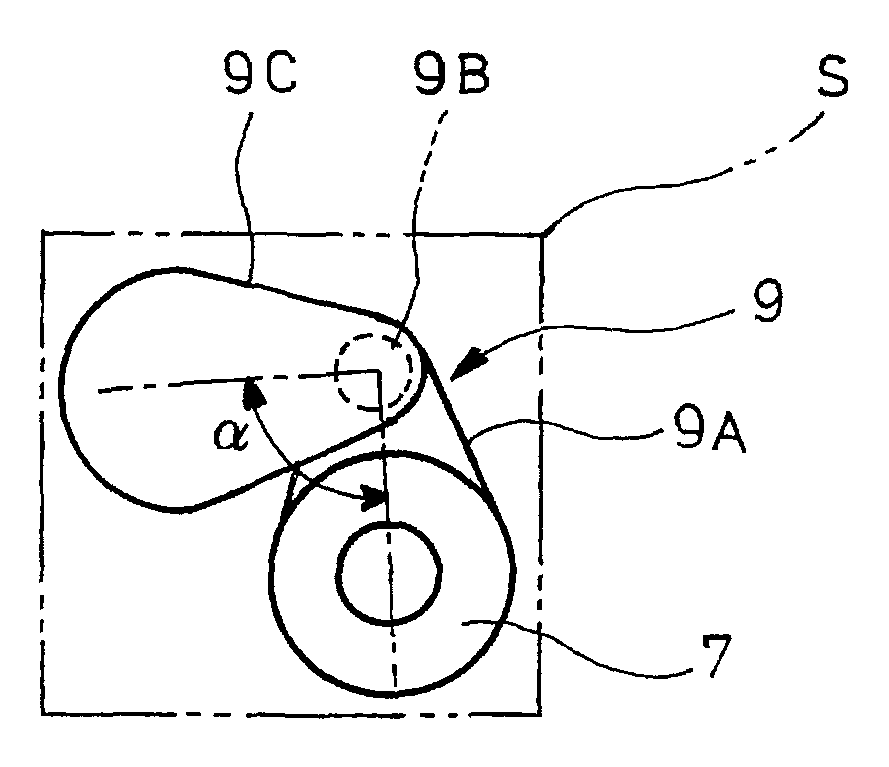
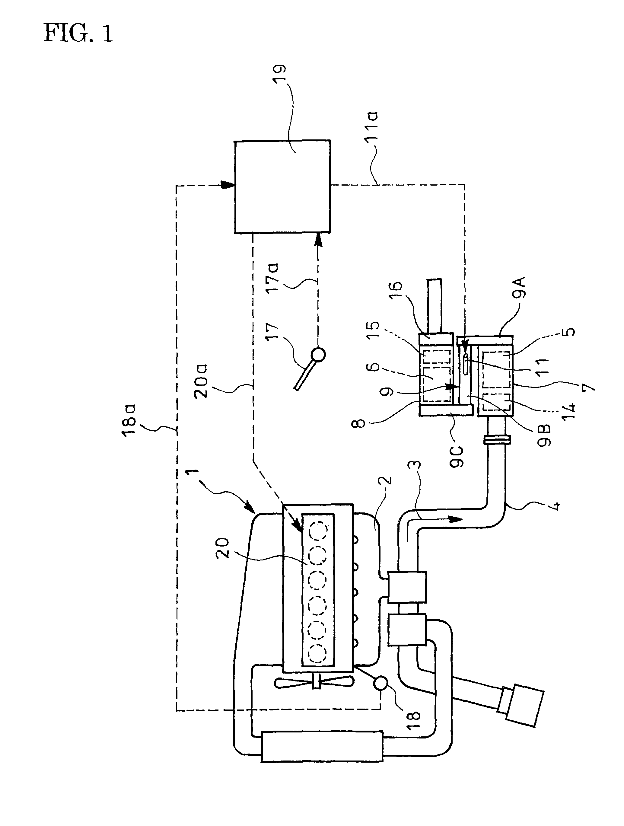
[0039]FIG. 1 shows the embodiment of the invention. In the embodiment of the exhaust emission control device, incorporated in an exhaust pipe 4 through which exhaust gas 3 flows from a diesel engine 1 via an exhaust manifold 2 is a particulate filter 5 housed in a casing 7 to capture particulates in the exhaust gas 3; arranged downstream of and in parallel with the particulate filter 5 and housed in a casing 8 is selective reduction catalyst 6 having a property capable of selectively reacting NOx with ammonia even in the presence of oxygen. A rear end of the particulate filter 5 is connected to an front end of the selective reduction catalyst 6 through an S-shaped communication passage 9 such that the exhaust gas 3 discharged through the rear end of the particulate filter 5 is passed via forward turnabout into the front end of the neighboring selective reduction catalyst6.

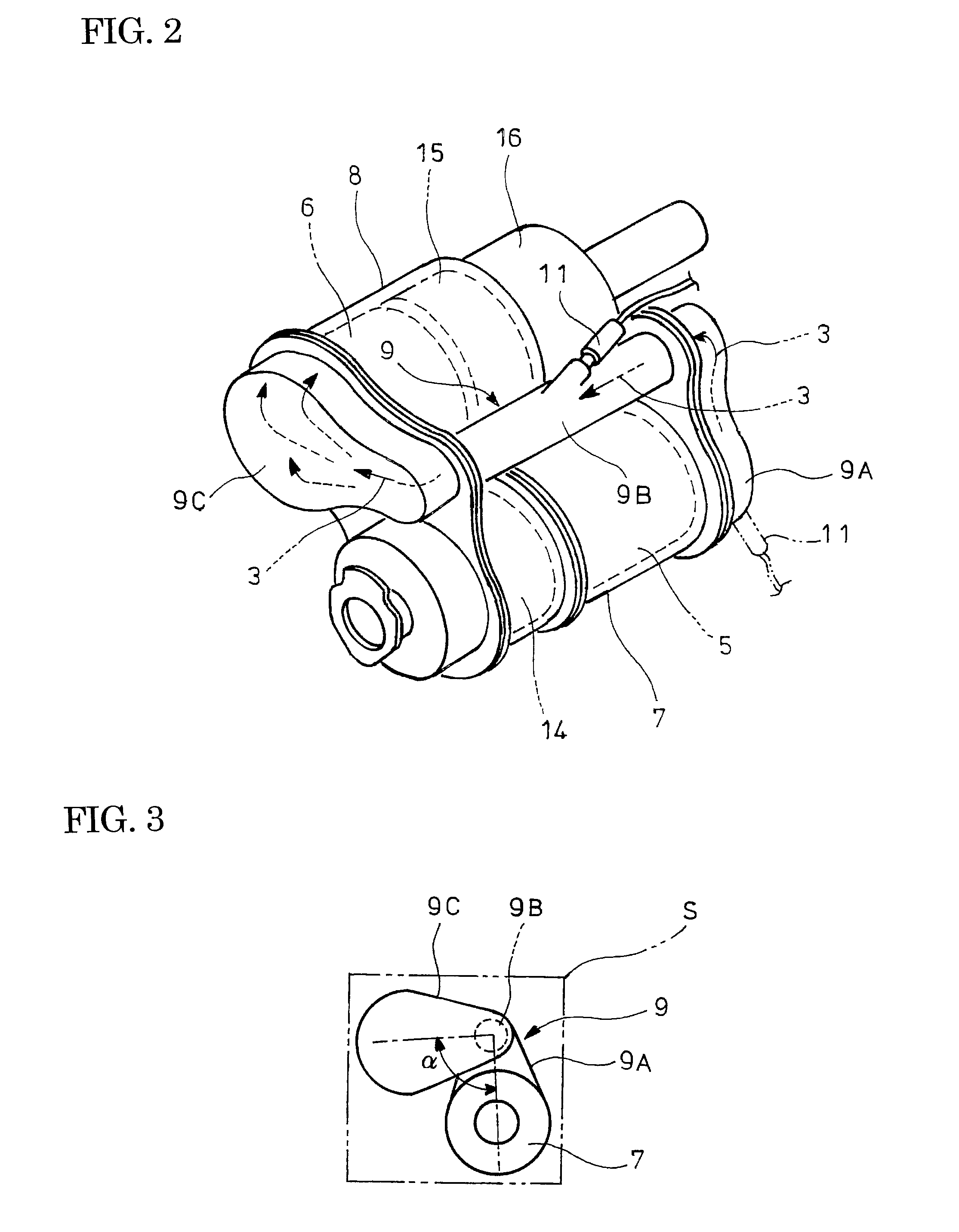
[0040]As shown in FIG. 2...


PUM

PropertyMeasurementUnit
crank angleaaaaaaaaaa
sizeaaaaaaaaaa

Abstract

An exhaust emission control device having a particulate filter incorporated in an exhaust pipe, a selective reduction catalyst capable of selectively reacting NOx with ammonia under the presence of oxygen being arranged downstream of the particulate filter, and urea water as a reducing agent which is adapted to be added between the selective reduction catalyst and the particulate filter is disclosed. The particulate filter is arranged in parallel with the selective reduction catalyst. An S-shaped communication passage is arranged for introduction of the exhaust gas from a rear end of the particulate filter to a front end of the adjacent selective reduction catalyst in a forward folded manner. An urea water addition injector is arranged midway of the communication passage.

Description

TECHNICAL FIELD[0001]The present invention relates to an exhaust emission control device.BACKGROUND ART[0002]Conventionally, some diesel engines have selective reduction catalyst incorporated in an exhaust pipe through which exhaust gas flow, said catalyst having a feature of selectively reacting NOx with a reducing agent even in the presence of oxygen. A required amount of reducing agent is added upstream of the reduction catalyst and is reacted on the catalyst with NOx (nitrogen oxides) in the exhaust gas to thereby reduce a concentration of the discharged NOx.[0003]Meanwhile, effectiveness of ammonia (NH3) used as a reducing agent for reduction and purification of NOx is well known in a field of industrial flue gas denitration, for example, in a plant. However, in a field of automobile where safety is hard to assure as to running with ammonia itself being loaded, researches have been made nowadays on use of nontoxic urea water as reducing agent.[0004]More specifically, when the u...

Claims


Application Information

Patent Timeline
Patent Type & Authority Patents(United States)
IPC IPC(8): F01N3/24
CPCB01D46/0027B01D46/0061B01D46/42F01N3/035F01N3/106F01N13/011F01N3/2892F01N13/009F01N3/2066B01D2279/30F01N2610/02F02D41/029Y02T10/24Y02A50/20Y02T10/12B01D46/82
Inventor KOWADA, MINORU
Owner HINO MOTORS LTD
Features
  • R&D
  • Intellectual Property
  • Life Sciences
  • Materials
  • Tech Scout
  • Unparalleled Data Quality
  • Higher Quality Content
  • 60% Fewer Hallucinations
Learn More