Temperature-control circuit of a heating line and a temperature-control method thereof
a technology of temperature control circuit and heating line, which is applied in the field of temperature control circuit, can solve the problems of increasing the manufacturing cost and achieve the effect of flexible adjustment of the heating temperatur
- Summary
- Abstract
- Description
- Claims
- Application Information
AI Technical Summary
Benefits of technology
Problems solved by technology
Method used
Image
Examples
first embodiment
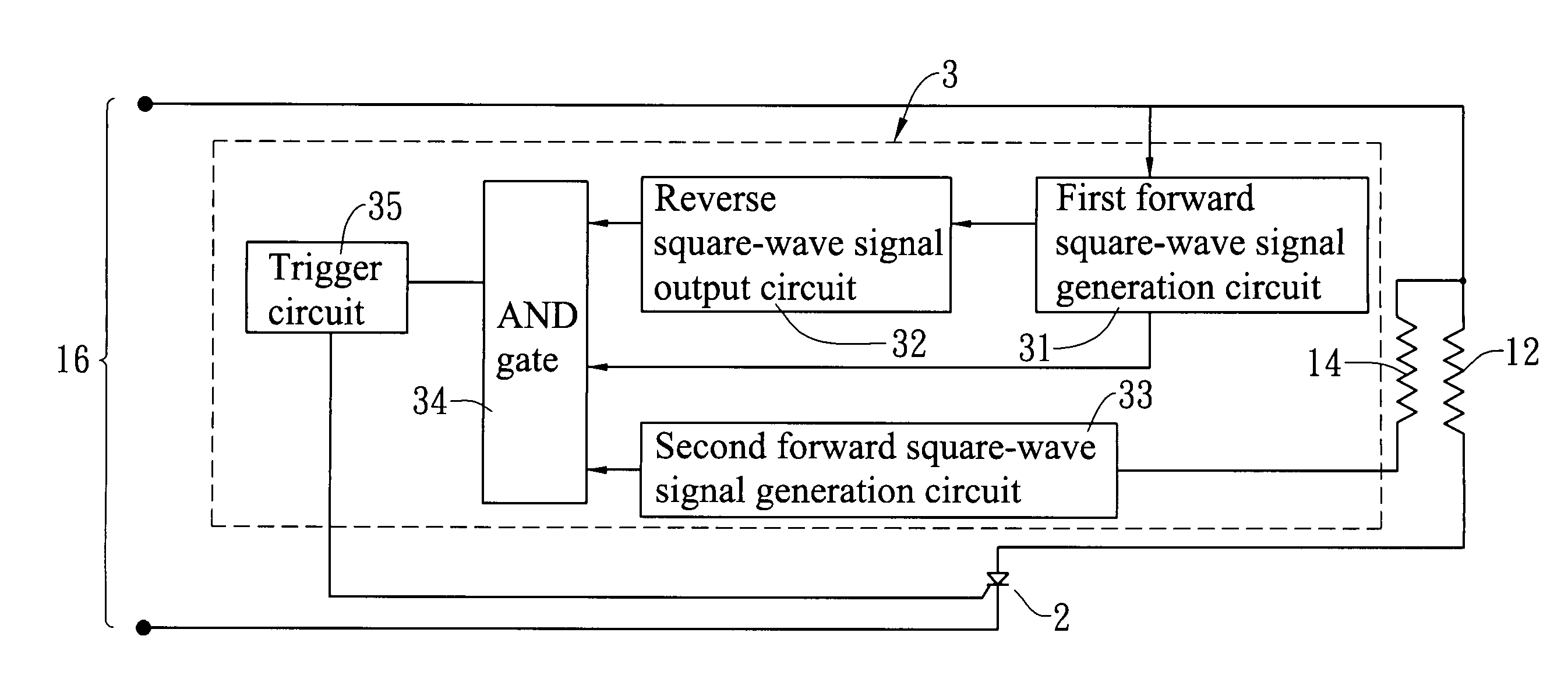
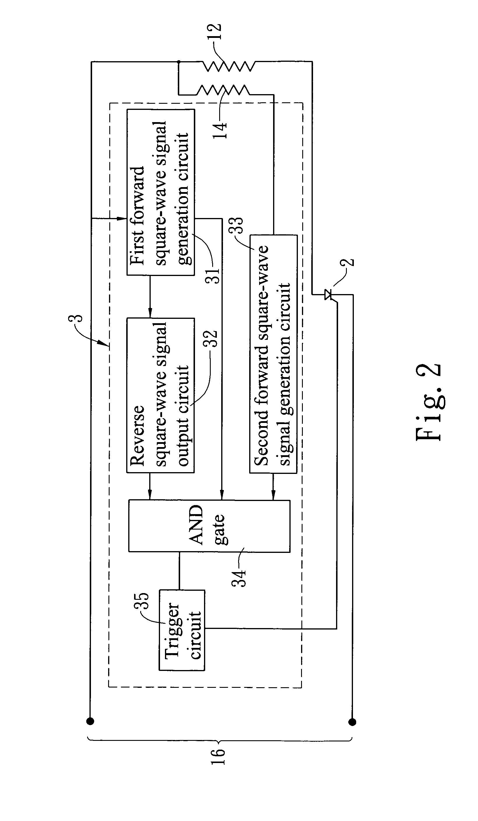
[0031]Please refer to FIG. 3 showing a circuit diagram of the temperature-control circuit 3 of the present invention. In this embodiment, the power 16 is an AC power for outputting a sine wave signal of 110 volts and 60 Hz. A sixth node P6 is provided between one polarity of the power 16 and the heating wire 12. Besides, one end of the sensing line 14 is coupled with the sixth node P6.
[0032]The first forward square-wave signal generation circuit 31 includes a resistor R5 and a diode D4 that are in serial connection. One end of the resistor R5 is coupled with one polarity of the power 16. The diode D4 has one end in ground connection. A seventh node P7 is provided between the resistor R5 and the diode D4. The non-inverting input end of the third voltage comparator U3A is coupled with the seventh node P7. The inverting input end of the third voltage comparator U3A is in ground connection so as to covert the sine wave signal to the first forward square-wave signal.
[0033]The reverse squ...
second embodiment
[0038]Please refer to FIGS. 7 and 8 showing the temperature-control circuit of the heating line according to the present invention. In this embodiment, the first forward square-wave signal generation circuit 31 further includes a fourth voltage comparator U4A. The non-inverting input end of the fourth voltage comparator U4A is coupled with the seventh node P7. The inverting input end of the fourth comparator U4A is in ground connection. The output end of the fourth voltage comparator U4A is coupled with one end of the sensing line 14. Thereby, the sine wave signal of the power 16 is output to be the forward square-wave signal via the fourth voltage comparator U4A. The forward square-wave signal is charged and discharged by the second RC circuit that is composed of the sensing line 14 and the second capacitor C2 and then is input into the second voltage comparator U2A so as to output the second forward square-wave signal.
third embodiment
[0039]Please refer to FIG. 9 showing the temperature-control circuit of the heating line according to the present invention. In this embodiment, the first forward square-wave signal generation circuit 31 is coupled with one end of the sensing line 14. The first forward square-wave signal generation circuit 31 is a square-wave signal generator used for outputting the first forward square-wave signal directly. In this case, the power 16 is an AC power and the switch 2 is a silicon-controlled-rectifier (SCR). Besides, the switch 2 also can be a thyristor, such as a TRIAC. In practice, the power 16 also can be a DC power and the switch can be a metal-oxide-semiconductor field-effect transistor (MOSFET).
[0040]Please refer to FIG. 10 showing a fourth embodiment of the temperature-control circuit of the heating line according to the present invention. This embodiment differs from the third embodiment in following aspects. A sixth node P6 is provided between one polarity of the power 16 and...
PUM
 Abstract
Description
Claims
Application Information
 - R&D
- Intellectual Property
- Life Sciences
- Materials
- Tech Scout
- Unparalleled Data Quality
- Higher Quality Content
- 60% Fewer Hallucinations
Browse by: Latest US Patents, China's latest patents, Technical Efficacy Thesaurus, Application Domain, Technology Topic, Popular Technical Reports.
© 2025 PatSnap. All rights reserved.Legal|Privacy policy|Modern Slavery Act Transparency Statement|Sitemap|About US| Contact US: help@patsnap.com


