Supercharge Your Innovation With Domain-Expert AI Agents!

Power semiconductor device

a technology of power semiconductor and semiconductor device, which is applied in the direction of printed circuit, sustainable manufacturing/processing, final product manufacturing, etc., can solve the problems of difficult to reduce the size of the power semiconductor device, low productivity, and long manufacturing time, and achieve high yield, excellent productivity, and reduce defects

Active Publication Date: 2012-08-28
MITSUBISHI ELECTRIC CORP
View PDF22 Cites 5 Cited by
  • Summary
  • Abstract
  • Description
  • Claims
  • Application Information

AI Technical Summary

Benefits of technology

The design reduces defects and stress at the terminal connections, increases current capacity, and improves productivity by dispersing stress and preventing gaps or cracks, resulting in a high-yield, reliable, and compact power semiconductor device capable of handling large currents.

Problems solved by technology

Thus, there are a large number of manufacturing processes, causing a prolonged manufacturing time.
Accordingly, there is a problem of low productivity.
Accordingly, there is a problem that it is difficult to reduce the size of the power semiconductor device.
In addition, since a bending process is performed on the lead frames that are used as the external terminals, there is a limitation regarding the thickness thereof.
Thus, there is a problem that an increase in the current is limited in the power semiconductor device.
Due to this stress, there is a problem that defects occur at the main terminal area, for example, a gap occurs at a joint surface between the outer side surface of the main terminal and the transfer molding resin, or fine cracks occur in the transfer molding resin.
This causes problems of low yield, low productivity, and low reliability of the power semiconductor device.
These problems are more prominent when the connection to the external wiring is formed by thread connection.
Further, since a large current is applied, even if a cable is used for external wiring to be connected to the main terminal, the cable used herein is highly rigid.
Accordingly, the same problems occur.

Method used


Image

  • Power semiconductor device
  • Power semiconductor device
  • Power semiconductor device

Examples


first embodiment

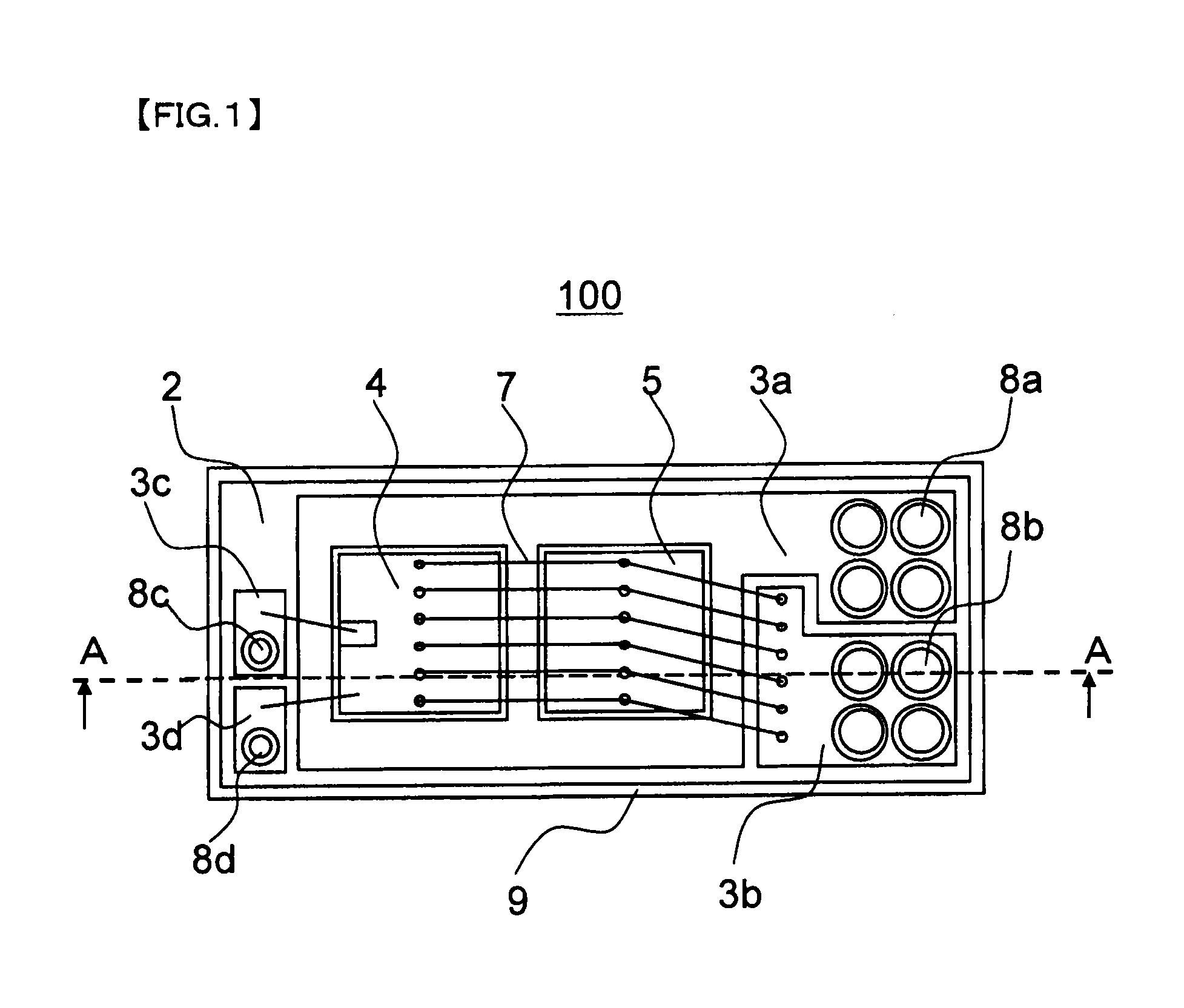
[0031]FIG. 1 is a schematic plane view showing that transfer molding resin on a circuit substrate of a power semiconductor device according to the first embodiment of the present invention, is removed.

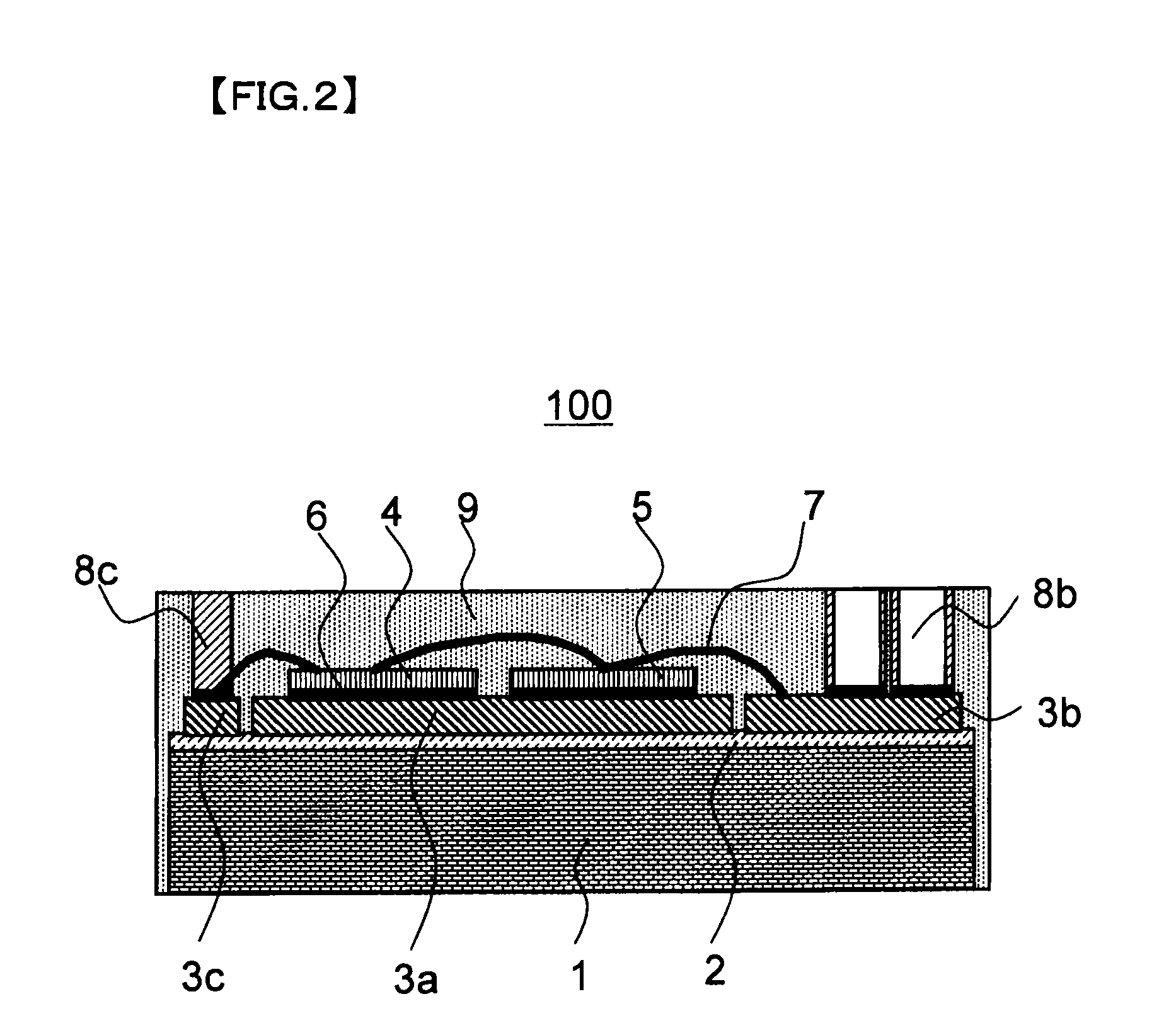
[0032]FIG. 2 is a schematic cross sectional view of the power semiconductor device shown in FIG. 1, which is cut along a line A-A indicated in FIG. 1 when the transfer molding resin is present on the circuit substrate.

[0033]As shown in FIGS. 1 and 2, in a power semiconductor device 100 of the present embodiment, a metal circuit substrate is used, which is formed such that: a resin insulation layer 2 is provided on one surface of a metal heat sink 1; and wiring patterns are provided on a surface of the resin insulation layer 2, which surface is opposite to a surface, of the resin insulation layer 2, joined to the metal heat sink 1. An IGBT 4 and a diode 5 connected in antiparallel with the IGBT 4, which are power semiconductor elements, are mounted on one of the wiring patterns. These p...

second embodiment

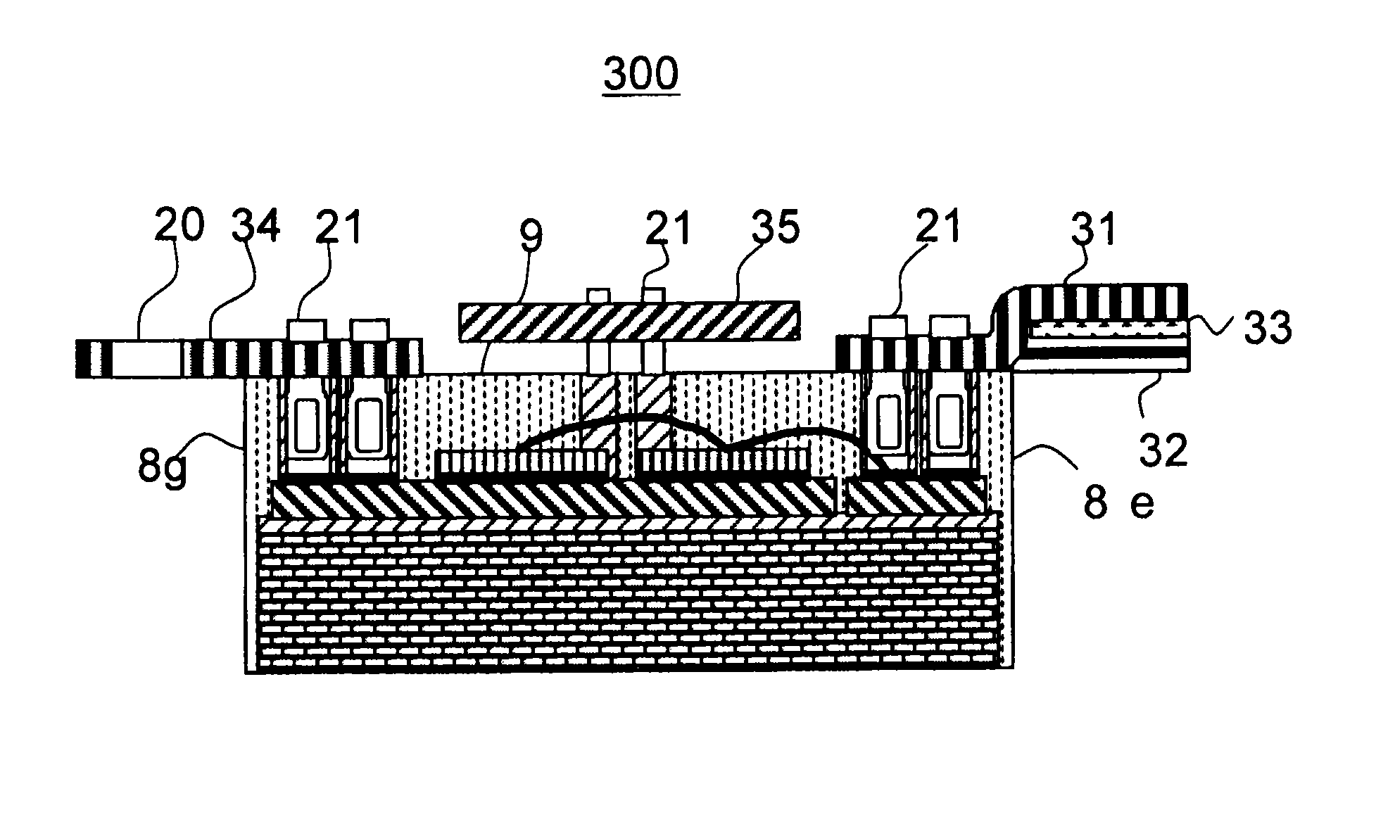
[0082]FIG. 4 is a schematic top view of a power semiconductor device according to the second embodiment of the present invention.

[0083]FIG. 5 is a schematic cross sectional view of the power semiconductor device shown in FIG. 4, which is cut along a line B-B indicated in FIG. 4.

[0084]In the present embodiment, a surface of the transfer molding resin 9, at which holes of cylindrical external terminal communication sections of the power semiconductor device are present, is referred to as a top surface.

[0085]As shown in FIGS. 4 and 5, a power semiconductor device 200 of the present embodiment is the same as the power semiconductor device 100 of the first embodiment except that in the present embodiment, external terminals 20 each provided with connecting pins 21 are connected to the cylindrical external terminal communication sections of the power semiconductor device 100 of the first embodiment. One external terminal connecting pin 21 is inserted into the cylindrical external terminal...

third embodiment

[0100]FIG. 7A is a schematic top view showing an external terminal 26 having four connecting pins to be connected to the cylindrical external terminal communication sections of each main circuit of a power semiconductor device according to the third embodiment of the present invention. FIG. 7B is a schematic cross-sectional view which is cut along a line D-D indicated in the schematic top view of FIG. 7A.

[0101]Here, a surface of the plate portion 22 of the external terminal 26, which is the opposite surface to a surface having connecting pins 21 protruding therefrom, is referred to as a top surface.

[0102]The power semiconductor device of the present embodiment (not shown) is the same as the power semiconductor device 200 of the second embodiment except that external terminals 26, each of which has four connecting pins 21 and in each of which the plate portion 22 and the connecting pins 21 are integrated, are used.

[0103]As shown in FIGS. 7A and 7B, in each external terminal 26 of the...


PUM


Abstract

A power semiconductor device includes power semiconductor elements joined to wiring patterns of a circuit substrate, cylindrical external terminal communication sections, and wiring means for forming electrical connection between, for example, the power semiconductor elements and the cylindrical external terminal communication sections. The power semiconductor elements, the cylindrical external terminal communication sections, and the wiring means are sealed with transfer molding resin. The cylindrical external terminal communication sections are arranged on the wiring patterns so as to be substantially perpendicular to the wiring patterns, such that external terminals are insertable and connectable to the cylindrical external terminal communication sections, and such that a plurality of cylindrical external terminal communication sections among the cylindrical external terminal communication sections are arranged two-dimensionally on each of wiring patterns that act as main circuits.

Description

CROSS-REFERENCE TO RELATED APPLICATIONS[0001]The present application is a continuation of U.S. application Ser. No. 12 / 504,225 filed Jul. 16, 2009, and is based upon and claims the benefit of priority from prior Japanese Patent Applications No. 2008-186603 filed Jul. 18, 2008, the contents of each of which are incorporated herein by reference in their entirety.BACKGROUND OF THE INVENTION[0002]1. Field of the Invention[0003]The present invention relates to a resin-sealed power semiconductor device, formed by transfer molding, which is excellent in terms of productivity. The present invention particularly relates to a resin-sealed power semiconductor device, formed by transfer molding, which is small in size, realizes operation with a large current, and is highly reliable.[0004]2. Description of the Background Art[0005]A power semiconductor device capable of operating with a large current and a high voltage, which is able to efficiently discharge heat, which is generated by the operat...

Claims


Application Information

Patent Timeline
Patent Type & Authority Patents(United States)
IPC IPC(8): H01L23/48
CPCH01L23/3121H01L24/48H01L24/49H01L25/072H05K3/32H01L24/28H01L24/29H01L24/45H01L25/162H01L2224/45124H01L2224/48091H01L2224/48137H01L2224/48227H01L2224/48472H01L2224/48699H01L2224/4911H01L2224/49111H01L2224/49171H01L2224/49175H01L2224/73265H01L2924/01004H01L2924/01005H01L2924/01012H01L2924/01013H01L2924/01014H01L2924/01015H01L2924/0102H01L2924/01028H01L2924/01029H01L2924/01061H01L2924/01075H01L2924/01078H01L2924/01082H01L2924/014H01L2924/10253H01L2924/10272H01L2924/13055H01L2924/13091H01L2924/19043H01L2924/30107H05K3/284H05K2201/1031H05K2201/10333H05K2201/10962H01L2224/32225H01L2924/01006H01L2924/01033H01L2924/1815H01L2924/12032H01L2924/1305H01L2924/00014H01L2924/00H01L2924/00012H01L2924/3512H01L2224/48139H01L2224/45015H01L2924/15787H01L2224/0603H01L2924/181H01L24/73H01L2224/05553Y02P70/50
Inventor OI, TAKESHIOKA, SEIJIOBIRAKI, YOSHIKOUSUI, OSAMUNAKAYAMA, YASUSHI
Owner MITSUBISHI ELECTRIC CORP
Features
  • R&D
  • Intellectual Property
  • Life Sciences
  • Materials
  • Tech Scout
  • Unparalleled Data Quality
  • Higher Quality Content
  • 60% Fewer Hallucinations
Learn More