Camera image georeferencing systems

a georeferencing system and camera technology, applied in the field of camera image georeferencing systems, can solve the problems of inability to introduce synthetic landmarks into the scene, inability to reduce and inability to achieve the effect of reducing the number of off-line processing requirements and improving the quality of encompassing triangular elements resulting from at least one triangular mesh generation operation

Active Publication Date: 2012-08-28
PURETECH SYST
View PDF19 Cites 29 Cited by
  • Summary
  • Abstract
  • Description
  • Claims
  • Application Information

AI Technical Summary

Benefits of technology

[0018]Additionally, it provides such a method further comprising the steps of generating at least one (X,Y,Z,R) lookup table for such at least one camera model. Also, it provides such a method of Claim 9 further comprising the step of reducing off-line processing requirements by deferring the steps subsequent to such generating of the augmented principal nodelist to on-line operation. In addition, it provides such a method wherein step (b) further comprises the steps of: generating, for the augmented principal nodelist, at least two triangular element lists; wherein each of such at least two triangular element lists comprises a different initial exterior point of the convex hull, in camera space, of the augmented principal nodelist; locating, within each of such at least two triangular element lists, encompassing triangular elements comprising an excessively large angle; for each such encompassing triangular element comprising the excessively large angle, replacing such encompassing triangular element with an encompassing element from an alternative element list of such at least two triangular element lists; wherein the quality of encompassing triangular elements resulting from the at least one triangular mesh generation operation may be improved. And, it provides such a method further comprising the steps of: identifying, in camera space, a target blob comprising a discrete region of camera space associated with at least one target of the camera view; determining for the target blob, at least one blob attribute in camera space, such at least one blob attribute at least comprising pixel coordinates of a lowest blob point and pixel coordinates of a blob centroid point; mapping the pixel coordinates of such lowest blob point to a terrain point using such at least one camera model; computing a range value, rlow, comprising the distance from such terrain point to the virtual camera point; associating the same range value Rlow to the blob centroid point; intersecting the ray extending through the pixel coordinates of the blob centroid point with a sphere centered on the virtual camera point and comprising a radius equal to Rlow, disambiguating the result by selecting from at least one resulting intersection of such ray, a ray-end point that exhibits the lowest Z coordinate value, wherein coordinates of such ray-end point comprise the location of the at least one target in object space.

Problems solved by technology

Traditionally, such camera networks require a labor-intensive deployment and monitoring by human security personnel.
Human-monitored systems are, in general, relatively costly and prone to human error.
Additionally, georeferencing with a single camera, demands the presence of landmark-rich scene which may not be forthcoming in many instances, such as in the surveillance of ports and harbors, or when a site is being remotely monitored and it is not feasible to introduce synthetic landmarks into the scene.

Method used


Image

  • Camera image georeferencing systems
  • Camera image georeferencing systems
  • Camera image georeferencing systems

Examples


Embodiment Construction

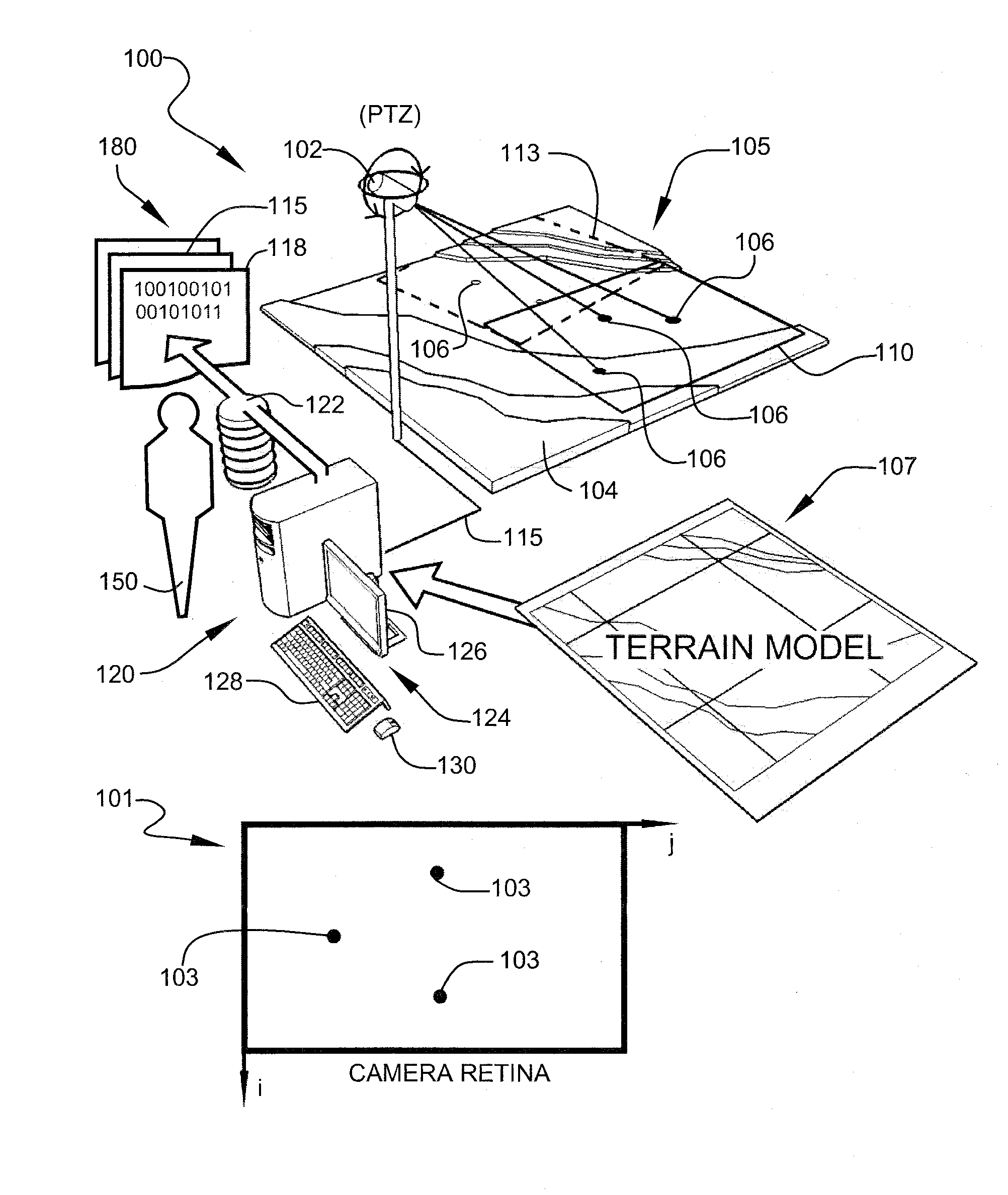
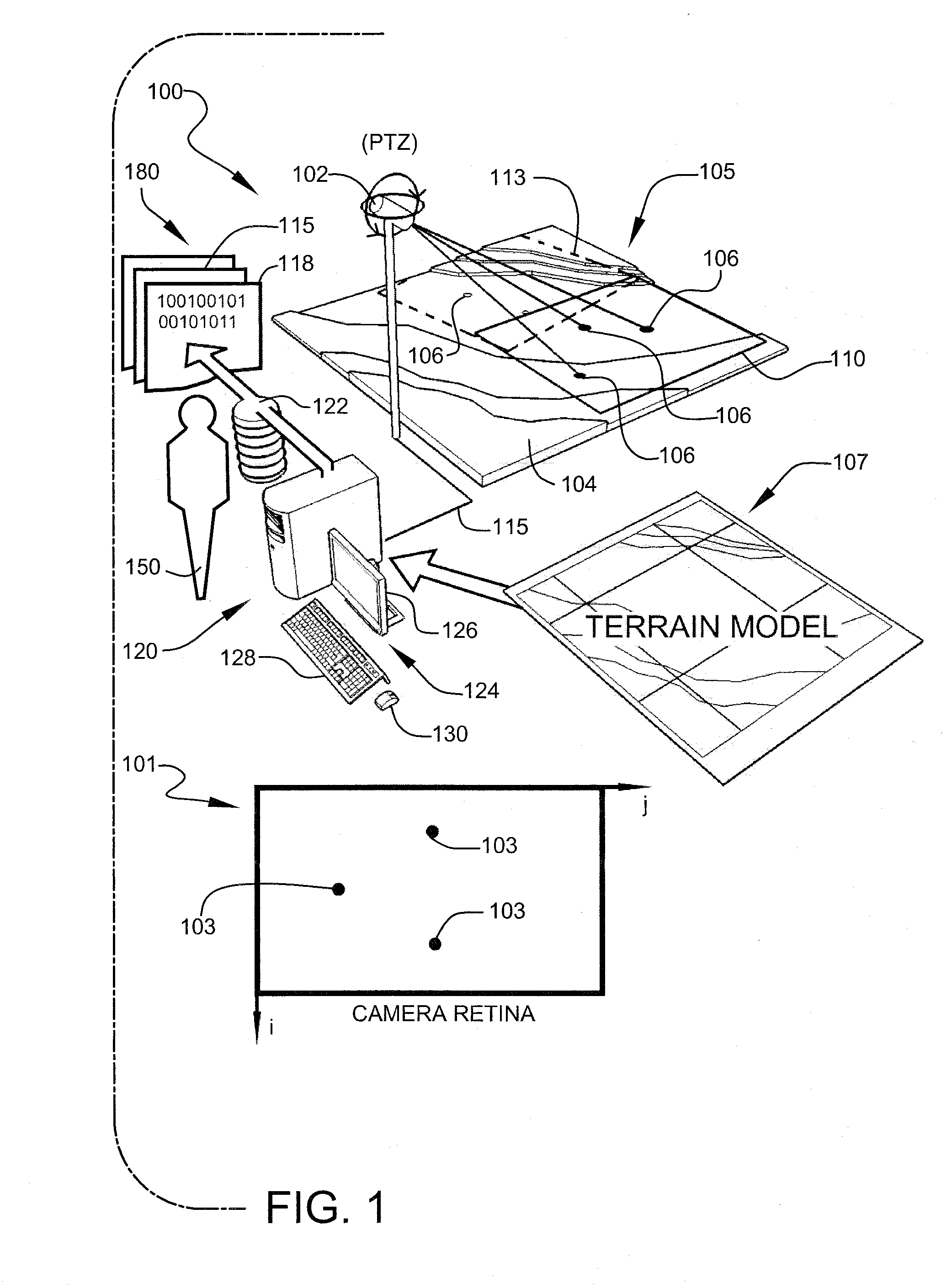
[0035]FIG. 1 shows a high-level schematic diagram illustrating a typical configuration for implementing georeferencing system 100, according to a preferred embodiment of the present invention. Preferred embodiments of georeferencing system 100 preferably enable construction of at least one camera model 180, through a preferred calibration process, and deployment of resulting models for georeferencing targets located in camera space 101. Camera space, as intended in this disclosure, is a two-dimensional abstraction of the physical terrain as imaged by the “retina” of camera 102, and in this disclosure comprises a left-handed coordinate system with its origin at the top left-hand corner of the image. It is noted that camera space, image space, pixel space, and retina space are used interchangeably throughout this disclosure. Conversely, the term objects space, as used herein, describes a frame of reference associated with the physical world. Object space, terrain space, geospatial spa...


PUM


Abstract

A method for constructing a georeferencing-enabled camera model and its deployment in georeferencing targets located in video sequences due to a single video camera. A video surveillance camera is modeled by a collection of rays converging at a virtual camera point and the retina resolution cell coordinates associated with those rays wherein the ray equations are first established, in the course of a calibration process, for a given camera view, with the aid of other views of the same video surveillance camera, as necessary, and using such a model for mapping image coordinates to terrain coordinates and vice versa in the intended view or its adaptation for use in other views of the same video surveillance camera.

Description

CROSS-REFERENCE TO RELATED APPLICATION[0001]The present application is related to and claims priority from prior provisional application Ser. No. 60 / 892,979, filed Mar. 5, 2007, entitled “GEOREFERENCING VIDEO TRACKS”, the content of which is incorporated herein by this reference and is not admitted to be prior art with respect to the present invention by the mention in this cross-reference section.BACKGROUND[0002]This invention relates to providing a system for improved camera image georeferencing. More particularly, this invention relates to providing a system for constructing at least one georeferencing-enabled camera model and its deployment in georeferencing targets located in video sequences utilizing a single video camera.[0003]The usefulness of video surveillance systems is becoming increasingly acknowledged as the demand for enhanced safety has increased. Areas commonly covered by such systems, include, for example, monitoring of harbors, airports, bridges, power plants, par...

Claims


Application Information

Patent Timeline
Patent Type & Authority Patents(United States)
IPC IPC(8): H04N7/18
CPCG06T7/0042G06T7/0018G01C2011/36G06T2207/10016G06T2207/30232G06T7/80G06T7/73G01C11/36
Inventor MAALI, FEREYDOUNTHOMAS, MONROE M.
Owner PURETECH SYST
Why Eureka
Try Eureka