
Selection of encoded data, setting of encoded data, creation of recoded data, and recoding method and device

a technology of encoded data and recoding method, applied in the direction of code conversion, color television with bandwidth reduction, television system, etc., can solve the problem of forming a special visible pattern in an image, the compatibility with the mpeg-2 recoding device using the present system may be greatly broken, and the method of item 2 cannot help being employed, so as to suppress the lack ratio of the amount of information of the encoded data

Active Publication Date: 2012-08-28
NEC CORP
View PDF12 Cites 2 Cited by
  • Summary
  • Abstract
  • Description
  • Claims
  • Application Information

AI Technical Summary

Benefits of technology

[0038]In the encoded data output method, the bit distribution step may reduce the predetermined type of encoded data which is not selected at the encoded data selection step.
[0063]The encoded data output method according to the present invention includes the prediction mode determination step for determining whether or not a prediction mode applied to the macroblocks is a predetermined prediction mode, the encoded data selection step for selecting a predetermined type of encoded data corresponding to the pixels at predetermined positions in the macroblocks to which the predetermined prediction mode is applied, and the bit distribution step for more preferentially distributing bits to a predetermined type of encoded data selected at the encoded data selection step than a predetermined type of encoded data that is not selected at the encoded data selection step in the macroblocks to which the predetermined prediction mode is applied. Accordingly, it is possible to suppress the number of bits of the encoded data per each macroblock to less than a predetermined value as well as to limit the encoded data per one macroblock transmitted from the decoding device to the recoding device to less than a predetermined value while suppressing the lack ratio of the amount of information of the encoded data as much as possible by properly setting a predetermined prediction mode, and a predetermined type of encoded data corresponding to the pixels at the predetermined positions in the macroblocks or a combination of them.

Problems solved by technology

Although the method of the item 1) is easy, when data is further multiplexed, it is contemplated that a disadvantage such as formation of a special visible pattern in an image, and the like.
Further, it is also contemplated that compatibility with an MPEG-2 recoding device making use of a present system may be greatly broken.
As a result, the method of the item 2) cannot help being employed.
When the method of the item 2) is employed, there is a possibility that an object of “suppressing deterioration of image quality as much as possible” cannot be achieved when data is disposed by an easy-going manner (that is, “easy-going data reduction”).

Method used


Image

  • Selection of encoded data, setting of encoded data, creation of recoded data, and recoding method and device
  • Selection of encoded data, setting of encoded data, creation of recoded data, and recoding method and device
  • Selection of encoded data, setting of encoded data, creation of recoded data, and recoding method and device

Examples


example 1

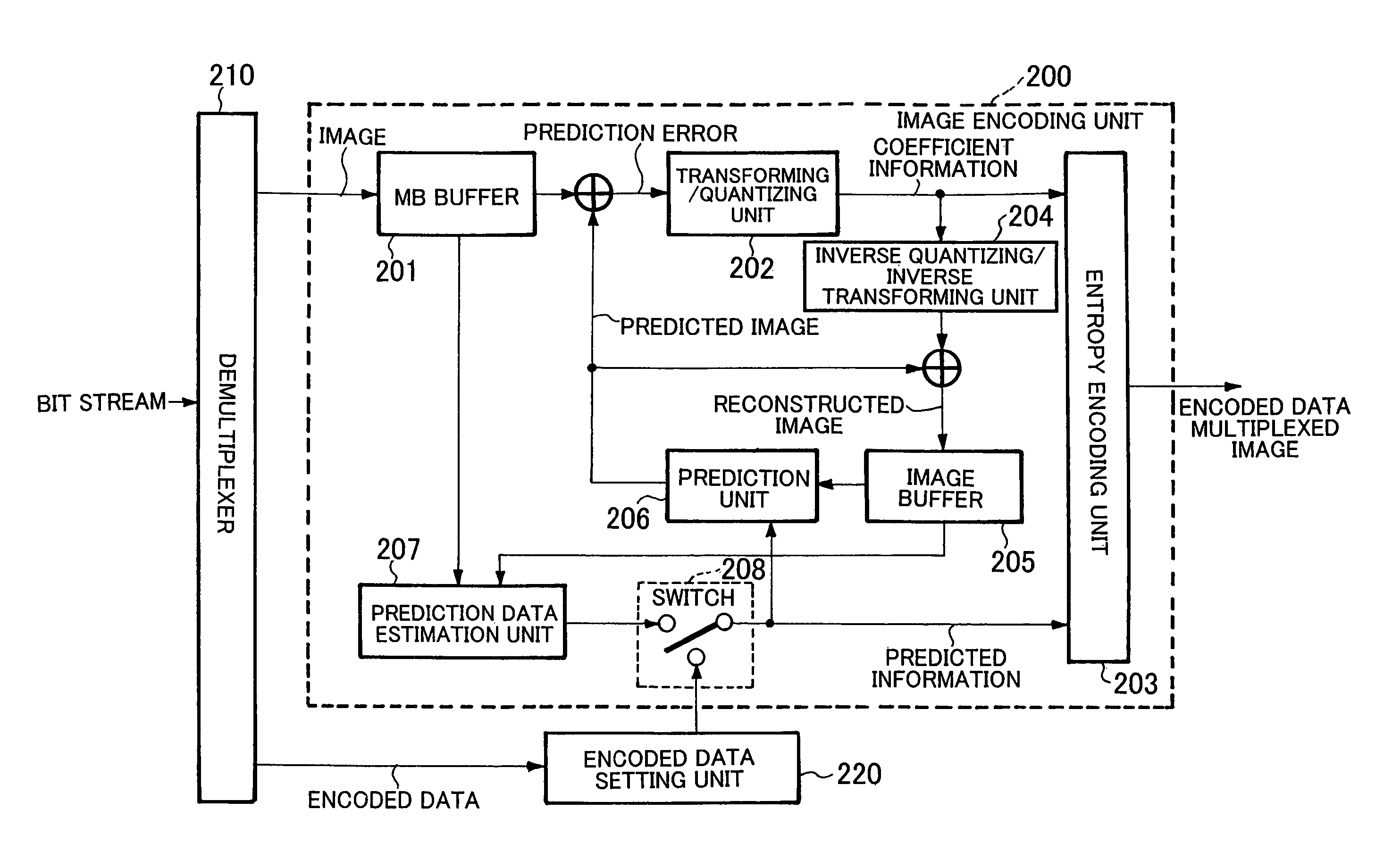
[0082]Referring to FIG. 4, an image decoding device with an encoded data multiplexing function according to the embodiment has an image decoding unit 100, a multiplexer 110, and an encoded data selection unit 120 as a characteristic unit of the present invention.

[0083]The image decoding unit 100 includes an entropy decoding unit 101, an inverse quantization / inverse transformation unit 102, an image buffer 103, and a prediction unit 104. Operation of the image decoding unit 100 will be explained below.

[0084]The entropy decoding unit 101 extracts coefficient information and prediction information by entropy decoding a bit stream input thereto.

[0085]The inverse quantization / inverse transformation unit 102 obtains a prediction error by inverse quantizing and inverse transforming the coefficient information supplied from the entropy decoding unit 101.

[0086]The prediction unit 104 creates a predicted image from a reconstructed image stored in the image buffer 103 making use of the predict...

example 2

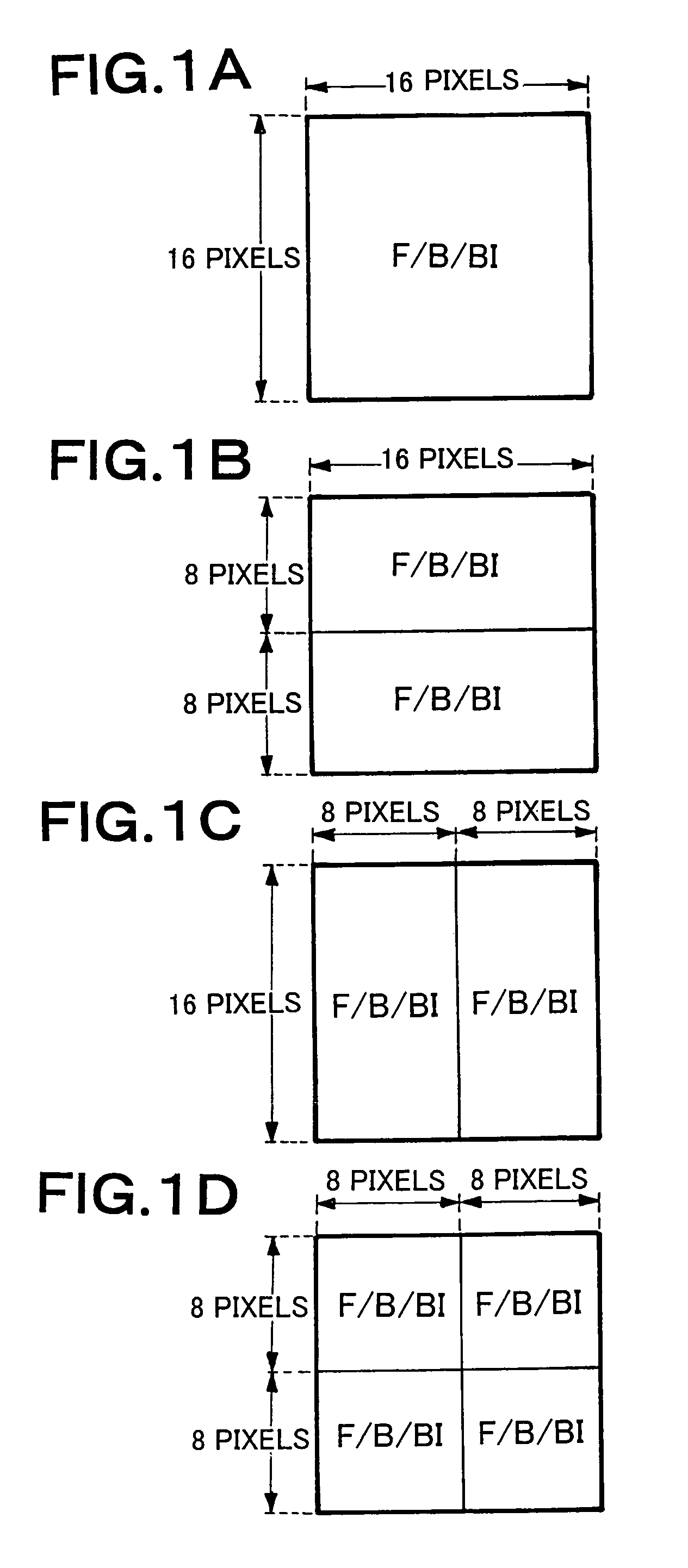
[0184]In the selection method of the motion vector employed in the example 1, all the motion vectors are discarded (no macroblock is selected) as to the submacroblock predicted in bidirection, although there are 8 macroblocks at the maximum per one macroblock from the beginning. With this operation, it is possible to set the number of bits of the encoded data per one macroblock to 161 at the maximum. However, when there is at least one submacroblock predicted in bidirection (ninth to twelfth columns of FIG. 11), a band with 256 bits per one macroblock is not sufficiently used. On the other hand, when motion vectors are transmitted as many as possible to the recode device, there is a possibility that the image quality of a restored image obtained from a bit stream output from the recoding device can be increased. However, when one motion vector is selected as to a submacroblock predicted in forward or backward direction and two motion vectors are selected as to each of 3 submacrobloc...


PUM


Abstract

In macroblocks to which a prediction mode determination step, which determines whether or not a prediction mode applied to the macroblocks is a predetermined prediction mode, and an encoded data selection step, which selects a predetermined type of encoded data corresponding to the pixels at predetermined positions in the macroblocks to which the predetermined prediction mode is applied, are applied, there is provided a bit distribution step for more preferentially distributing bits to a predetermined type of encoded data selected at the encoded data selection step than a predetermined type of encoded data that is not selected at the encoded data selection step in the macroblocks to which the predetermined prediction mode is applied. With these steps, it is possible to provide an encoded data selection method which can limit the encoded data per one macroblock transmitted from a decoding device to a recoding device to less than a predetermined value while suppressing the lack ratio of the amount of information of the encoded data as much as possible.

Description

BACKGROUND OF THE INVENTION[0001]1. Field of the Invention[0002]The present invention relates to an encoded data selection method and an encoded data setting method corresponding to the above method as well as to devices of these methods. Further, the present invention relates to a recoded data creation method including an encoded data selection method and a device corresponding to the method. Further, the present invention relates to a recoding method including an encoded data setting method and a device corresponding to the method. For example, the encoded data selection method is a method of selecting a part of encoded data output from a decoding device.[0003]2. Description of the Related Art[0004]In an tandem-connected MPEG-2 recoding device that uses a decoded image of MPEG-2 bit stream output from an MPEG-2 decoding device as an input, there is a technology for transmitting encoded data in a bit stream after it is multiplexed to decoded image (refer to “SMPTE 319M-2000” (authe...

Claims


Application Information

Patent Timeline
Patent Type & Authority Patents(United States)
IPC IPC(8): H04N7/12H03M7/36H04N19/103H04N19/50H04N19/115H04N19/134H04N19/137H04N19/139H04N19/176H04N19/40H04N19/51H04N19/577H04N19/91
CPCH04N19/159H04N19/176H04N19/46H04N19/196H04N19/198H04N19/132H04N19/517H04N19/40H04N19/115H04N19/513H03M7/30
Inventor IKEDA, TOSHIYUKICHONO, KEIICHI
Owner NEC CORP
Learn More