
Coating apparatus and method

a coating apparatus and coating technology, applied in the field of coating apparatus, can solve the problems of consumption of back side cleaning organic solvents, and inability to completely prevent mist deposition, so as to reduce the consumption of solvents

Active Publication Date: 2012-09-04
TOKYO ELECTRON LTD
View PDF14 Cites 23 Cited by
  • Summary
  • Abstract
  • Description
  • Claims
  • Application Information

AI Technical Summary

Benefits of technology

The present invention provides a coating apparatus and method for reducing solvent consumption for cleaning the back side of a substrate. The apparatus includes a substrate holding member for holding the substrate in a horizontal state, a coating nozzle for supplying a coating liquid onto the front side of the substrate, a rotational driving unit for rotating the substrate holding member about a vertical axis at a first rotational speed to spread the coating liquid, a liquid film forming mechanism for forming a liquid film on the substrate, a posture regulating mechanism for damping a vertical wobble of the substrate, and a control section for controlling the operation of the coating apparatus. The method includes holding the substrate in a horizontal state, supplying the coating liquid onto the front side of the substrate, rotating the substrate holding member about a vertical axis at a first speed to spread the coating liquid, supplying a process liquid onto the substrate to form a liquid film, and damping the vertical wobble of the substrate. The apparatus and method provide a more efficient way to apply coatings to substrates and prevent contamination.

Problems solved by technology

Accordingly, consumption of organic solvents for such back side cleaning is a problematic issue.
However, in this case, deposition of mist cannot be completely prevented, and so the solvent consumption for back side cleaning is still not so small.
Jpn. Pat. Appln. KOKAI Publication No. 2-16447 (FIG. 1) discloses a coating apparatus arranged to perform resist coating on a wafer in a floating state, but this apparatus cannot solve the problem described above.

Method used


Image

  • Coating apparatus and method
  • Coating apparatus and method
  • Coating apparatus and method

Examples


Embodiment Construction

[0048]An embodiment of the present invention will now be described in detail with reference to the accompanying drawings.

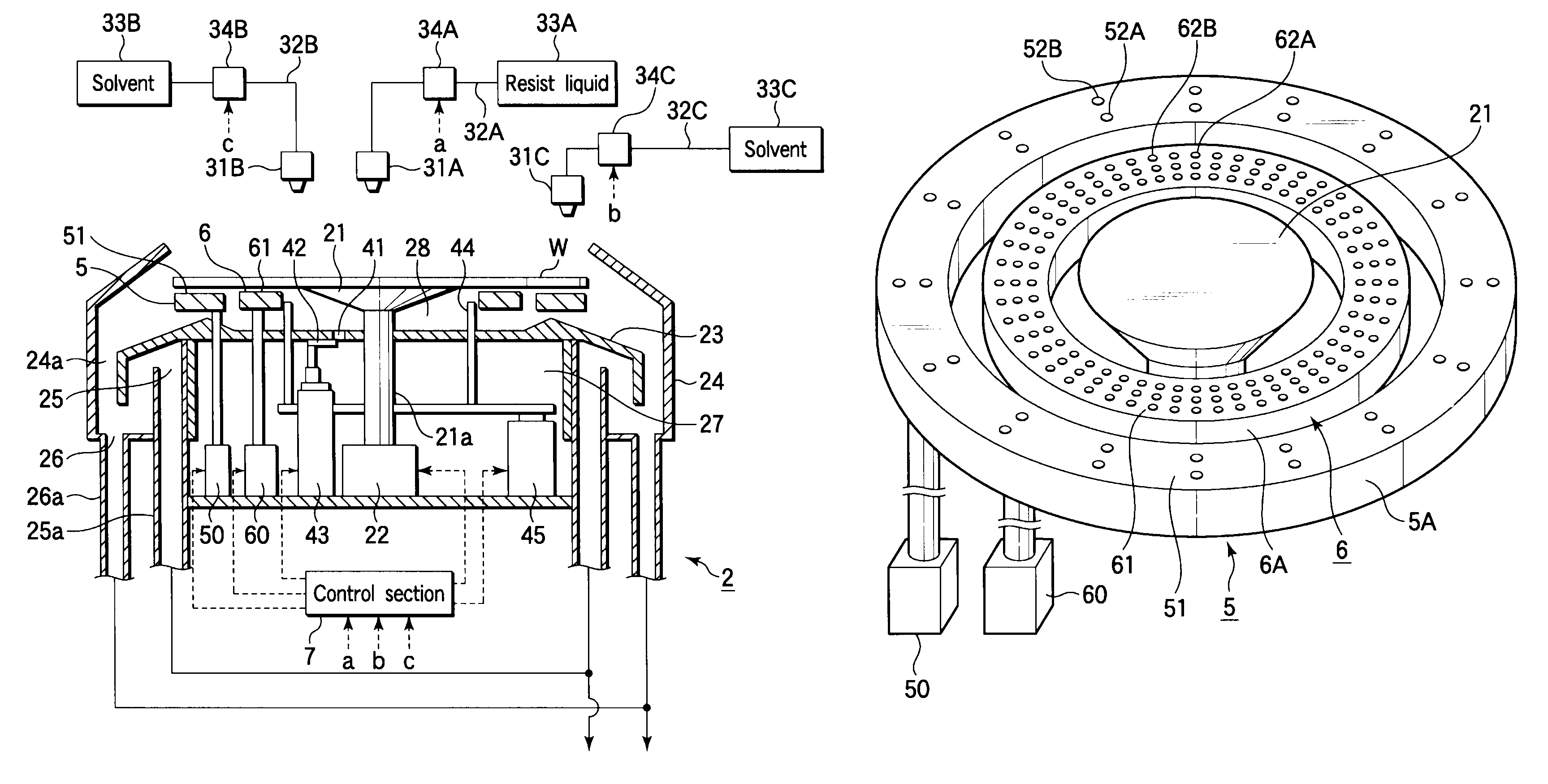
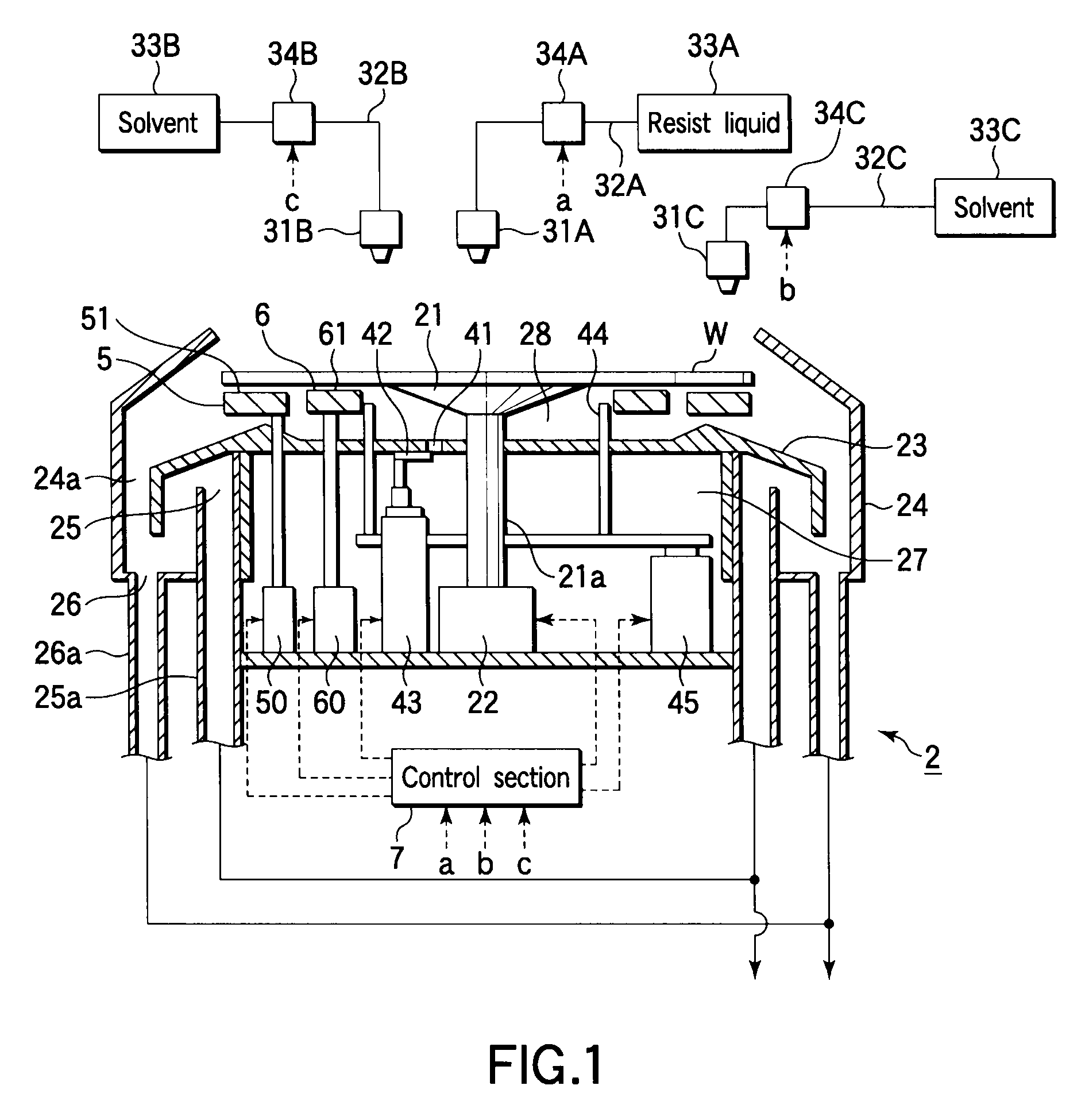
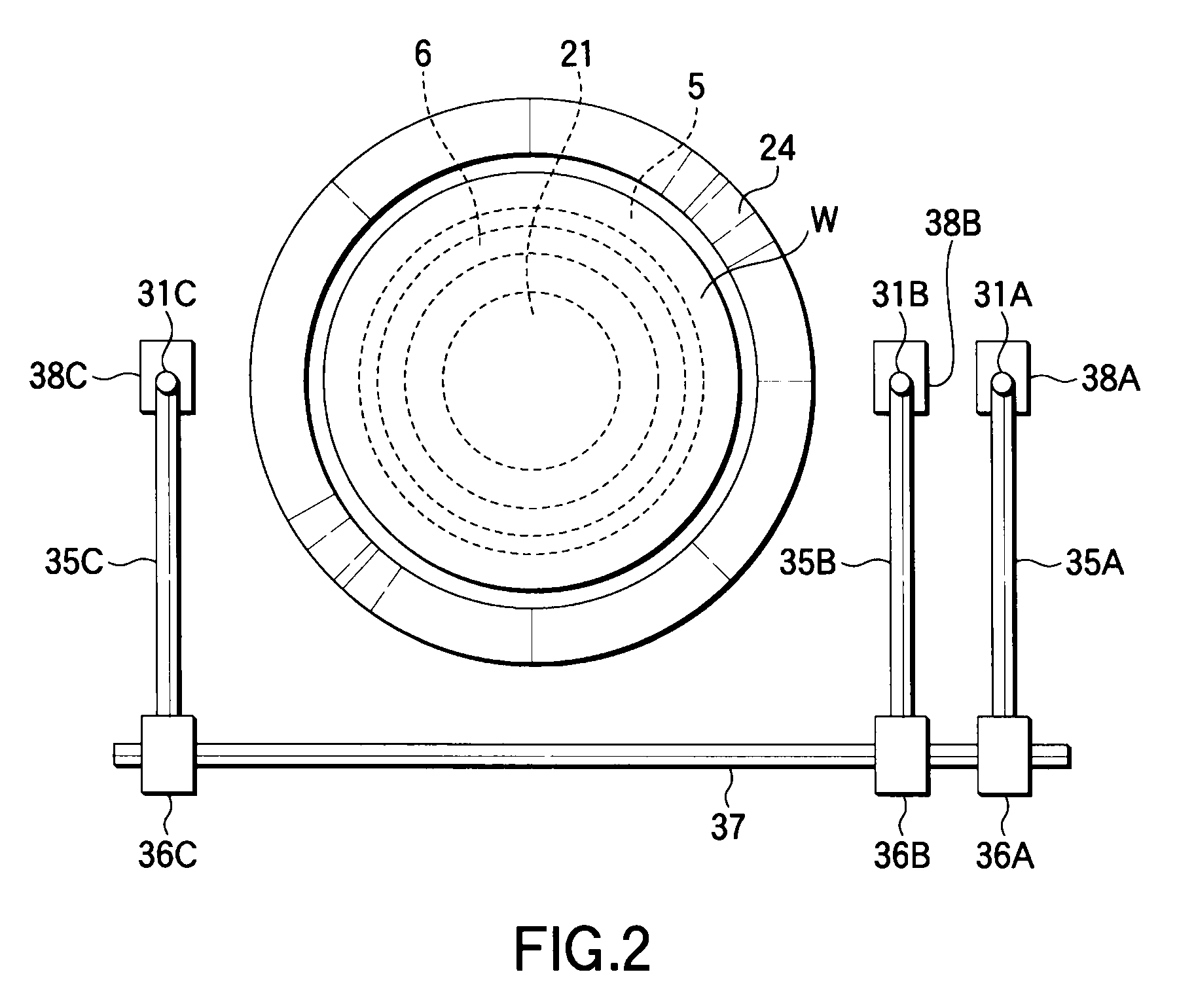
[0049]At first, an explanation will be given of a resist coating apparatus 2, which is a coating apparatus according to an embodiment of the present invention, with reference to FIGS. 1 and 2. FIGS. 1 and 2 are sectional side view and sectional plan view showing the resist coating apparatus 2. As shown in FIG. 1, a spin chuck 21 serving as a substrate holding member is disposed to hold a wafer W in a horizontal state by a vacuum attraction. The spin chuck 21 is rotatable about a vertical axis by a rotational driving unit 22 including a motor or the like through a connecting portion 21a. A partition plate 23 having an essentially circular shape is disposed below the spin chuck 21 to partition the resist coating apparatus 2 into upper and lower sides. The peripheral portion of the partition member or partition plate 23 has a convex shape in the cross section with th...


PUM


Abstract

A coating apparatus includes a liquid film forming mechanism configured to form a liquid film of a process liquid for preventing a contaminant derived from a coating liquid from being deposited or left on a back side peripheral portion of a substrate. The liquid film forming mechanism includes a counter face portion facing the back side peripheral portion of the substrate and a process liquid supply portion for supplying the process liquid onto the counter face portion. The coating apparatus further includes a posture regulating mechanism disposed around the substrate holding member and configured to damp a vertical wobble of the peripheral portion of the substrate being rotated. The posture regulating mechanism includes delivery holes arrayed in a rotational direction of the substrate and configured to deliver a gas onto a back side region of the substrate on an inner side of the peripheral portion.

Description

BACKGROUND OF THE INVENTION[0001]1. Field of the Invention[0002]The present invention relates to a coating apparatus and method for applying a chemical liquid, such as a resist, onto a substrate, such as a semiconductor wafer. The present invention also relates to a coating / developing apparatus including the coating apparatus and a storage medium that stores a program for executing the coating method.[0003]2. Description of the Related Art[0004]In the process of manufacturing semiconductor devices, there is a step of applying a coating liquid onto a substrate by a spin coating method. The coating liquid may be exemplified by a resist, a chemical liquid for forming an anti-reflection film, and a chemical liquid containing a precursor of silicon oxide for forming an insulating film. The spin coating method is arranged to use a spin chuck to attract and hold the back side central portion of a substrate, such as a semiconductor wafer (which may be simply referred to as “wafer”) or a LCD...

Claims


Application Information

Patent Timeline
Patent Type & Authority Patents(United States)
IPC IPC(8): B05C11/02B05C5/00B05C13/02B05C13/00B05B13/04B05C21/00B65G53/16B65G53/00B65G53/26B65G69/06
CPCG03F7/162G03F7/3021H01L21/6715H01L21/6838H01L21/67051H01L21/027G03F7/70908G03F7/70933H01L21/67017
Inventor KITANO, TAKAHIROOBATA, KOICHIINADA, HIROICHIOGATA, NOBUHIRO
Owner TOKYO ELECTRON LTD
Learn More