Liquid crystal geometrical phase optical elements and a system for generating and rapidly switching helical modes of an electromagnetic wave, based on these optical elements

a technology of geometrical phase optical elements and electromagnetic waves, which is applied in the field of optical elements, can solve the problems of limiting the application of optical components to the mid-infrared domain, not allowing any switching, and holographic components normally have the drawback of simultaneously generating a plurality of diffraction orders, so as to achieve the effect of fast switching of the helicity sta

Inactive Publication Date: 2012-09-11
CONSIGLIO NAT DELLE RICERCHE
View PDF2 Cites 84 Cited by
  • Summary
  • Abstract
  • Description
  • Claims
  • Application Information

AI Technical Summary

Benefits of technology

[0028]Briefly, the present invention is based on the general principle of producing “geometrical phase” optical components, or “Pancharatnam-Berry optical elements,” for wavefront shaping (for example, lenses, beam splitters, holographic components), operating in the visible and near infrared domain and using as a birefringent means a liquid crystal whose optical axis—corresponding to the molecular director—can be controlled easily, for example by the application of external fields or surface treatments.
[0031]Conveniently, for certain specific applications, PBOE's can have various advantages over normal optical components, including, in particular, a uniform and very small thickness, and switchability of the wavefront generated on the basis of the input polarization.
[0035]Unlike the systems commonly used for helical mode generation in the visible or near infrared domain, the system proposed by the invention makes it possible to control the helicity of the wavefront of the generated light (in other words, whether the helix is right-handed or left-handed) by using the polarization state of the incident light, instead of by using the geometry of the apparatus, thus permitting fast switching which is impossible with the known methods.
[0037]The system proposed by the invention is simple and efficient in terms of energy conversion and can be applied advantageously in the transmission of conventional or quantum information, encoded in the helicity state of the phase profile of light.

Problems solved by technology

However, holographic components normally have the drawback of simultaneously generating a plurality of diffraction orders with different wavefronts in addition to the desired wavefront.
The only PBOE's produced up to the present are based on optical gratings with a pitch smaller than the wavelength (known as “subwavelength gratings”), which limits their application to the mid-infrared domain, using the fabrication methods available today.
This method does not allow any switching and provides a helical beam with a substantially locked helicity.
If it is desired to switch the helicity of a single beam, it is necessary to modify the hologram (which can be done by using holograms generated in a computer-controlled spatial phase modulator, although this does not allow switching rates faster than a few hundreds of hertz), or to modify the direction from which the incident beam arrives.
Fast switching can therefore be achieved only by switching the incoming beam between a plurality of beams arriving from different directions, giving rise to obvious problems of complexity and wastage of optical energy.
Furthermore, the generation efficiency of holographic methods is no greater than 70%; in other words, they waste at least 30% of the light energy of each incident beam.
Thus all of these methods for generating helical modes in the visible or near infrared domain have the same limitation: they do not allow fast switching of the state of helicity or “order” of the helical mode.
This limitation is particularly serious where possible communications applications are concerned.

Method used


Image

  • Liquid crystal geometrical phase optical elements and a system for generating and rapidly switching helical modes of an electromagnetic wave, based on these optical elements
  • Liquid crystal geometrical phase optical elements and a system for generating and rapidly switching helical modes of an electromagnetic wave, based on these optical elements
  • Liquid crystal geometrical phase optical elements and a system for generating and rapidly switching helical modes of an electromagnetic wave, based on these optical elements

Examples


Embodiment Construction

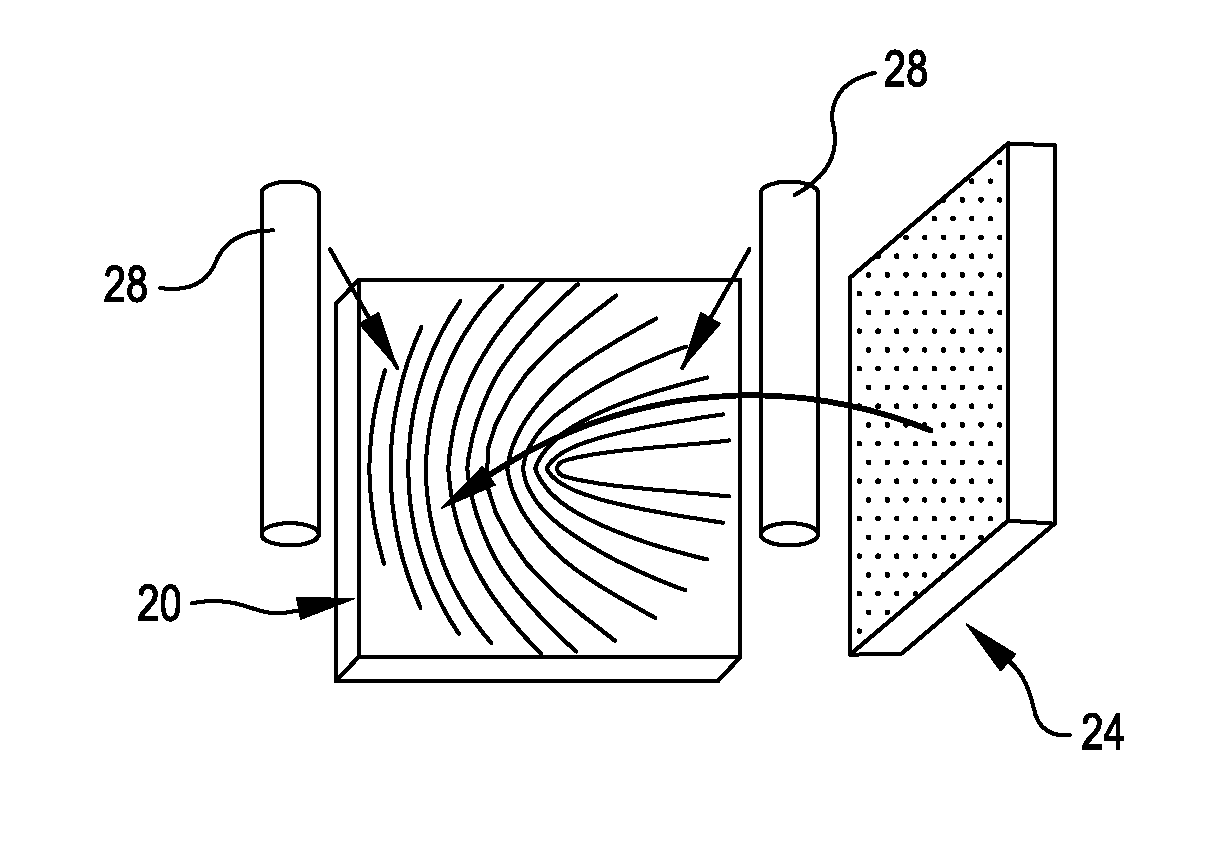
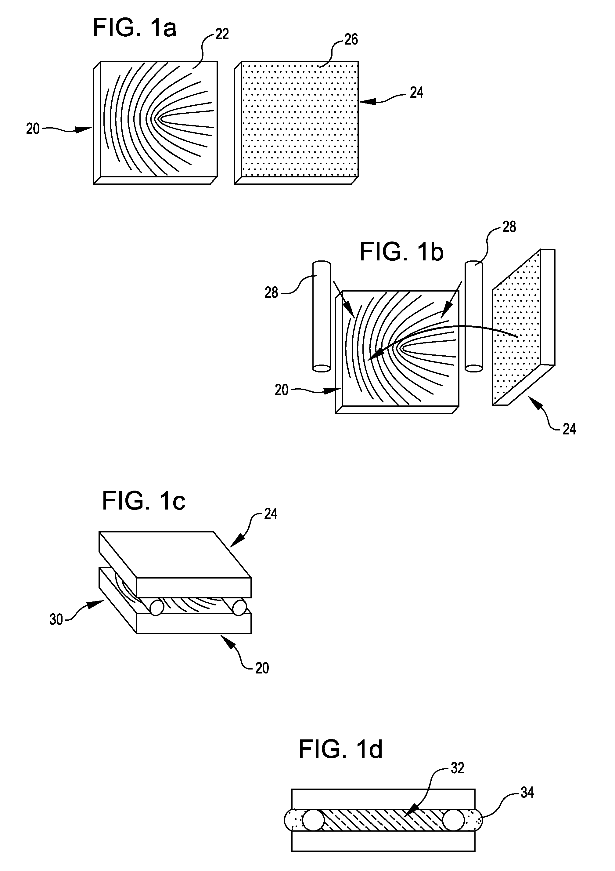
[0046]The description of the invention is based on a specific class of geometrical phase optical components, composed of half-wave birefringent means whose optical axis is spatially inhomogeneous in a plane orthogonal to the propagation direction of an incident optical beam, in an embodiment shaped as plates whose optical axis is spatially inhomogeneous in the plane of the plate (referred to below as “half-wave PBOE's”).

[0047]We will consider a plane birefringent plate orientated perpendicularly to the direction z of propagation of the light. It is assumed that the plate causes a phase shift of π (half wave) between the extraordinary and ordinary components of the light, in a homogeneous way throughout the plate, and that the optical axis (for example the “fast” axis) of the plate is inhomogeneous in the transverse plane xy (but homogenous in the direction z). Let α(x,y) be the angle formed by the optical axis of the plate with the reference axis x in the plane xy.

[0048]If we disreg...


PUM

PropertyMeasurementUnit
wavelengthsaaaaaaaaaa
wavelength rangeaaaaaaaaaa
phaseaaaaaaaaaa

Abstract

Geometrical phase optical elements comprising, as a birefringent means, a liquid crystal material with a spatially inhomogeneous orientation of the molecular director in a plane orthogonal to the direction of propagation of an input radiation beam, ordered according to a predetermined geometrical pattern. Also, an optical system for generating helical modes of propagation of an optical radiation beam, including a geometrical phase optical element orientated transversely to the direction of propagation of the beam, whose optical axis is orientated according to a predetermined geometrical relation adapted to transform a circular polarized input radiation beam into a helical mode with a wavefront having a helical surface whose handedness is a function of the handedness of the input polarization, in which the switching between different orders of helicity of the radiation beam emerging from the geometrical phase optical element is carried out by switching the circular polarization state of the input radiation.

Description

CROSS-REFERENCES TO RELATED APPLICATIONS[0001]This application claims priority to International Patent Application No. PCT / IB2007 / 051441, filed Apr. 20, 2007 and priority to Italian application TO2006A000303 filed Apr. 26, 2006, the full disclosures of which are incorporated herein by reference.BACKGROUND OF THE INVENTION[0002]The present invention relates to optical components for shaping the wavefront of a beam of electromagnetic radiation, and to their use in the field of optical communications for information encoding, particularly for optical communications in the visible or near infrared spectrum.[0003]More specifically, the invention relates to the production of geometrical phase optical components and the use of these optical components for generating helical modes of an optical electromagnetic wave.[0004]Optical components for wavefront shaping are normally based on a suitable spatial modulation of the length of the optical path travelled by different portions of the wavefr...

Claims


Application Information

Patent Timeline
Patent Type & Authority Patents(United States)
IPC IPC(8): G02F1/1335
CPCG02F1/0305G02F1/0322G02F2203/18
Inventor MARRUCCI, LORENZO
Owner CONSIGLIO NAT DELLE RICERCHE
Why Eureka
Try Eureka