Ear thermometer and measuring apparatus used with it

a technology of ear thermometer and measuring apparatus, which is applied in the direction of optical radiation measurement, instruments, spectrophotometry/monochromators, etc., can solve the problems of difficult to keep the accuracy of the thermistor for a wide range of ambient temperatures, temperature difference occurs to prevent a correct measurement, and the output of the probe is temporarily destabilized, etc., to achieve easy mass production and easy installation

Active Publication Date: 2012-09-18
BIO ECHO NET
View PDF21 Cites 0 Cited by
  • Summary
  • Abstract
  • Description
  • Claims
  • Application Information

AI Technical Summary

Benefits of technology

[0021]An object of the present invention is to provide an ear thermometer that is based on the ear thermometer of Patent Document 2 and has sensors that are configured to be easily installed in a sensor mirror, so that the ear thermometer is easily mass-producible.
[0033]According to the ear thermometer of the present invention, the sensor (thermistor) used for the probe is required to secure an accuracy only for a temperature range in which the body temperature of a measuring object varies. Unlike the conventional ear thermometer using a thermopile, the thermistor is not required to keep an accuracy for an entire measuring ambient temperature range. When an ambient temperature is relatively stable, it can carry out a continuous measurement for a long period of time. The sensor is soldered to the circuit conductor of the flexible printed circuit board, to simplify assembling work. This is advantageous for mass production. With the simplified temperature measuring circuit, simplified temperature calibration, and compact probe, the ear thermometer is small and inexpensive. The ear thermometer according to the present invention, therefore, is disposable and is stably and surely attachable to the ear of a measuring object. Accordingly, it is optimum for measuring, in particular, the body temperature of a measuring object during an operation.
[0034]According to the measuring apparatus for an ear thermometer of the present invention, the program write mode (flash mode) of the microcontroller incorporated in the measuring apparatus and the run mode to execute a written program are switched from one to another without using a mode switch of the microcontroller. Instead, the flash mode is established if a voltage applied to the test port of the microcontroller is HIGH, and if it is LOW, the run mode is established. Accordingly, only by preparing a program write unit that applies the HIGH voltage to the test port of the microcontroller and by connecting the program write unit to the connector of the measuring apparatus, the microcontroller is automatically shifted to the flash mode. As a result, the measuring apparatus for an ear thermometer according to the present invention needs no mode switch for the microcontroller, thereby simplifying a circuit configuration and miniaturizing the apparatus.
[0035]According to the measuring apparatus for an ear thermometer of the present invention, the mode switching circuit may employ the transistor. In this case, the first resistor is arranged between the common voltage line and the collector of the transistor, to set a voltage of the collector to the HIGH voltage when the transistor is in a conductive state. The second resistor is interposed between the base of the transistor and the output of the regulator, so that, when the transistor is OFF, a leakage current passes from the common voltage line through the first and second resistors to the output side of the regulator and combines with an output current of the regulator. This reduces an input current of the regulator itself by the leakage current in the run mode. As a result, the insertion of the mode switching circuit causes no substantial change in power consumption. This results in suppressing the power consumption of the apparatus and extending the power of the battery.
[0036]According to the measuring apparatus for an ear thermometer of the present invention, the mode switching circuit may employ the operational amplifier. In this case, the common voltage is set to a high voltage to invert the operational amplifier into a conductive state, so that the common voltage is outputted as the HIGH voltage to the test port of the microcontroller. When the common voltage is set to a low voltage, i.e., a battery voltage, the operational amplifier is again inverted into a nonconductive state so that the operational amplifier outputs the LOW voltage to the test port of the microcontroller. During the run mode of the microcontroller, which is a normal operating state of the microcontroller, no battery current is passed to the mode switching circuit. As a result, the insertion of the mode switching circuit causes no substantial change in power consumption. This results in suppressing the power consumption of the apparatus and extending the power of the battery.
[0037]According to the measuring apparatus for an ear thermometer of the present invention, the mode switching circuit may employ the CMOS inverter. In an operating state in which the CMOS inverter outputs the common voltage, the common voltage is supplied as the HIGH voltage to the test port of the microcontroller. When the CMOS inverter is inverted, the voltage of the regulator is set as the LOW voltage and is supplied to the test port of the microcontroller. In the run mode of the microcontroller, which is a normal operating state of the same, no battery current is passed to the mode switching circuit. As a result, the insertion of the mode switching circuit causes no substantial change in power consumption. This results in suppressing the power consumption of the apparatus and extending the power of the battery.

Problems solved by technology

If an external factor applies a sudden temperature change, a head of the package and the heat sink of the thermopile produce a temperature difference to transiently destabilize the output of the probe.
If thermal bonding between the thermopile cold junction and the thermistor is bad, a temperature difference occurs to prevent a correct measurement.
Even thermistors based on the same standard have different B-constants (the B-constant representing the magnitude of a resistance change obtained from temperatures at optional two points on a resistance-temperature characteristic curve), and therefore, it is difficult for the thermistor to keep accuracy for a wide range of ambient temperatures.
The ear thermometer according to Patent Document 1, however, has problems of hardly being miniaturized, consuming large power, involving a complicated circuit, and partly needing expensive parts to increase a total cost.
The ear thermometer according to Patent Document 1 is appropriate for once measuring a body temperature in a short period of time, but it is inappropriate for continuously measuring body temperatures for a long period of time.
Namely, if a warm-up time of certain extent (about 10 minutes) is allowed, if a large relative temperature and a quick temperature change are ignorable (if sensing a temperature change of 1° C. for 10 minutes at the maximum is sufficient), if continuous measurement is needed, and if ambient temperature is relatively stable, the ear thermometer according to Patent Document 1 is expensive and is inappropriate.
The ear thermometer according to Patent Document 2, however, is configured to support the first and second sensors with the lead wires in the sensor mirror, and therefore, the work to solder the sensors and lead wires together and the work to arrange the sensors in the sensor mirror need a high skill and a long time.
Accordingly, this ear thermometer is unsuitable for mass production.
Conventional ear thermometers have the problem that their measuring apparatuses are large in scale, and therefore, it is required to reduce the sizes thereof.Patent Document 1: Japanese Unexamined Patent Application Publication No. 2006-250883Patent Document 2: Japanese Unexamined Patent Application Publication No. 2007-111363

Method used


Image

  • Ear thermometer and measuring apparatus used with it
  • Ear thermometer and measuring apparatus used with it
  • Ear thermometer and measuring apparatus used with it

Examples


Embodiment Construction

[0055]Embodiments of the present invention will be explained in detail with reference to the drawings.

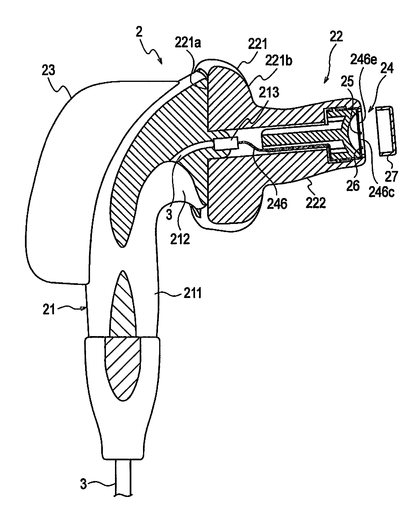
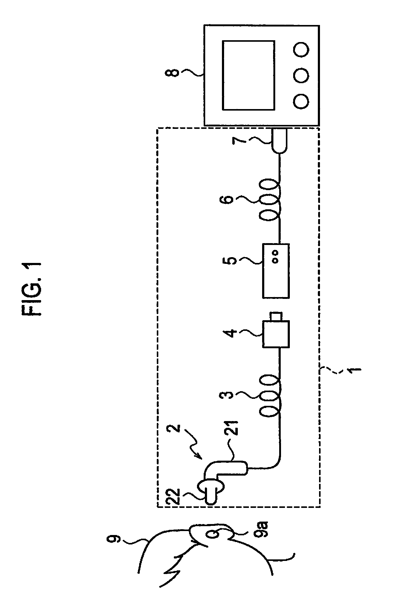
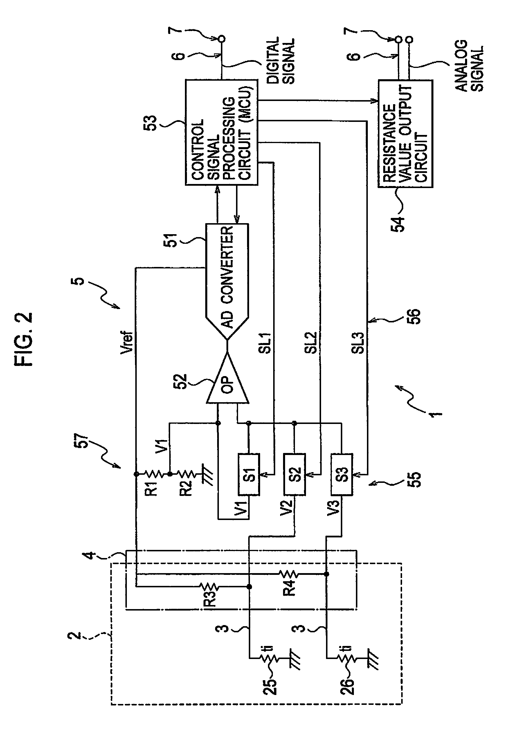
[0056]FIG. 1 illustrates a device configuration of an ear thermometer according to an embodiment of the present invention and FIG. 2 illustrates a circuit configuration thereof. As illustrated in FIG. 1, the ear thermometer 1 according to this embodiment has a probe 2 that is inserted into an ear hole of an object person, to measure the temperature of an eardrum and output a resistance value representative of the measured temperature, a cable 3 to transmit a measurement signal of the probe 2 and supply power to the probe 2, a male connector 4, a measuring apparatus 5 to perform a temperature measuring process and other control, a cable 6 connected to the measuring apparatus 5, and a female connector 7 connected to a front end of the cable 6. The female connector 7 connected to the cable 6 of the measuring apparatus 5 is connected to a monitor 8 to display a measured temperature.

[005...


PUM


Abstract

An object is to realize an ear thermometer that is configured to easily arrange a sensor in a sensor mirror and is suitable for mass production. The ear thermometer has a probe. The probe includes a probe body and a temperature measuring part joined with the probe body. The temperature measuring part includes a flange coupled with the probe body and a front end part extending from the flange, the front end part incorporating a sensor mirror. The sensor mirror includes a cylindrical holder with an internal concave reflection face, a connection shaft extending from the back of the cylindrical holder, a flexible printed circuit board with a circuit conductor of predetermined pattern, stretched in a front space of the cylindrical holder, a temperature measuring first sensor and a correcting second sensor spaced by a predetermined distance from each other in a longitudinal direction of the board and soldered to the circuit conductor on the board, and a protection cover covering a front face of the cylindrical holder. The board is electrically connected, in the temperature measuring part, to the cable passing through the probe body.

Description

TECHNICAL FIELD[0001]The present invention generally relates to a thermometer to measure the body temperature of a measuring object, and particularly, to an ear thermometer to measure a temperature of the eardrum by inserting a temperature sensing part into an ear hole and a measuring apparatus used with the ear thermometer.BACKGROUND TECHNOLOGY[0002]A typical example of a conventional ear thermometer will be explained with reference to FIGS. 15 and 16. FIG. 15 is a circuit block diagram illustrating an operation principle of the conventional ear thermometer and FIG. 16 is a vertical section of a temperature sensing part of the conventional ear thermometer. As illustrated in FIG. 15, a probe 10 of the typical conventional ear thermometer employs a thermopile 11. Generally, the thermopile produces a potential difference depending on a temperature difference between a cold junction and a hot junction (the Seebeck effect). Using the thermopile as a temperature measuring probe needs a r...

Claims


Application Information

Patent Timeline
Patent Type & Authority Patents(United States)
IPC IPC(8): G01J5/54
CPCG01J5/0011G01J5/02G01J5/0205G01J5/025G01J5/028G01J5/04G01J5/048G01J5/049G01J5/08G01J5/085G01J5/14H05K1/189G01J3/0202H05K2201/10606G01J2005/068H05K2201/09063H05K2201/10151G01J3/0243G01J5/064A61B5/01G01J5/00
Inventor TANAKA, HIDEKI
Owner BIO ECHO NET
Why Eureka
Try Eureka