Anchoring assembly part for a tower of a wind turbine

a technology of wind turbines and assembly parts, which is applied in the direction of engine fuctions, structural elements, building components, etc., can solve the problems of requiring a space-consuming head portion, requiring a steel-made tower portion with a concrete-made tower portion, and requiring constructionally sumptuous

Inactive Publication Date: 2012-09-25
NORDEX ENERGY
View PDF15 Cites 19 Cited by
  • Summary
  • Abstract
  • Description
  • Claims
  • Application Information

AI Technical Summary

Benefits of technology

[0016]Further advantages are provided by the prefabrication of the tower portion from a concrete material. In particular, the alignment of the anchoring system on the construction site is simplified. In contrast to a special head portion, which is cast on the construction site, the accurate alignment of the bores for the anchor bolts relative to each other can be made sure already before the construction of the tower. At the construction site, only the entire anchoring assembly part has to be brought into the correct position. This is possible in a simple way, by corresponding joining of the reinforcement elements to the reinforcement of the lower tower portion. A further advantage is that a concrete material with particularly high resistance to pressure can be selected in the production of the anchoring assembly part, independently from the selection of the concrete material for the lower tower portion. Through this, the connection to the steel-made tower portion is simplified, wherein a load distribution plate can be omitted according to circumstances.
[0018]In one embodiment, the at least one reinforcement element projects towards the downside from the anchoring assembly part. In principle, it may also project laterally from the anchoring assembly part, and be anchored in the concrete-made tower portion in this region. However, a joining of the reinforcement below the anchoring assembly part permits a particularly compact construction.
[0022]In one embodiment, the bores for accommodating the anchor bolts run in the axial direction of the anchoring assembly part. This indication of a direction is always related to an annular anchoring assembly part, like the direction indications below. Correspondingly, in a ring segment shaped anchoring assembly part, the direction indication is related to a virtually completed ring. In a cylindrical ring, the anchor bolts can be arranged accurately in the axial direction. In a ring formed slightly conical, corresponding to the concrete-made tower portion, it may also be deviated from the axial direction, corresponding to the inclination angle of the cone. In both cases, the alignment of the anchor bolts permits a particularly firm anchoring, with compact construction of the anchoring assembly part at the same time.
[0025]According to one embodiment, a sheath made of plastics is arranged in the at least one bore for receiving the anchor bolt, which receives the anchor bolt and which extends through the bore, starting from the anchor sleeve. In the casting of the anchoring assembly part, the sheath makes sure that the bore is arranged as desired and that the internal thread of the anchor sleeve remains clear. Besides, it prevents direct contact of the anchor bolt with the concrete.
[0028]According to one embodiment, the at least one anchor sleeve is arranged on a lower face of the anchoring assembly part. A maximum extraction resistance results from this arrangement.

Problems solved by technology

Particular difficulties arise in the connection of the steel-made tower portion with the concrete-made tower portion.
This known solution permits to replace the anchor bolts, but is constructionally sumptuous and requires a space-consuming head portion.

Method used


Image

  • Anchoring assembly part for a tower of a wind turbine
  • Anchoring assembly part for a tower of a wind turbine
  • Anchoring assembly part for a tower of a wind turbine

Examples


Embodiment Construction

[0034]While this invention may be embodied in many different forms, there are described in detail herein a specific preferred embodiment of the invention. This description is an exemplification of the principles of the invention and is not intended to limit the invention to the particular embodiment illustrated

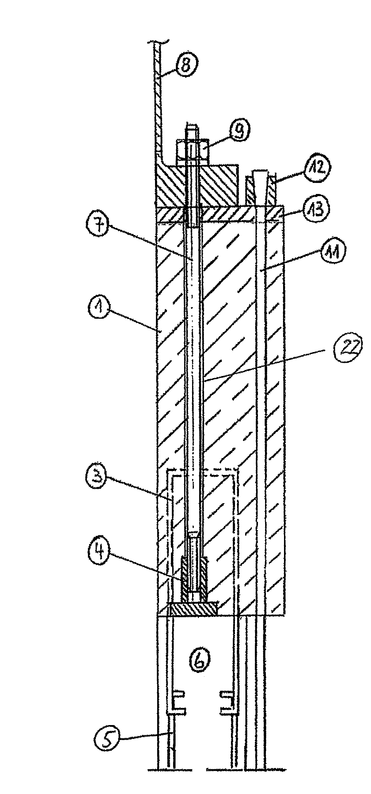
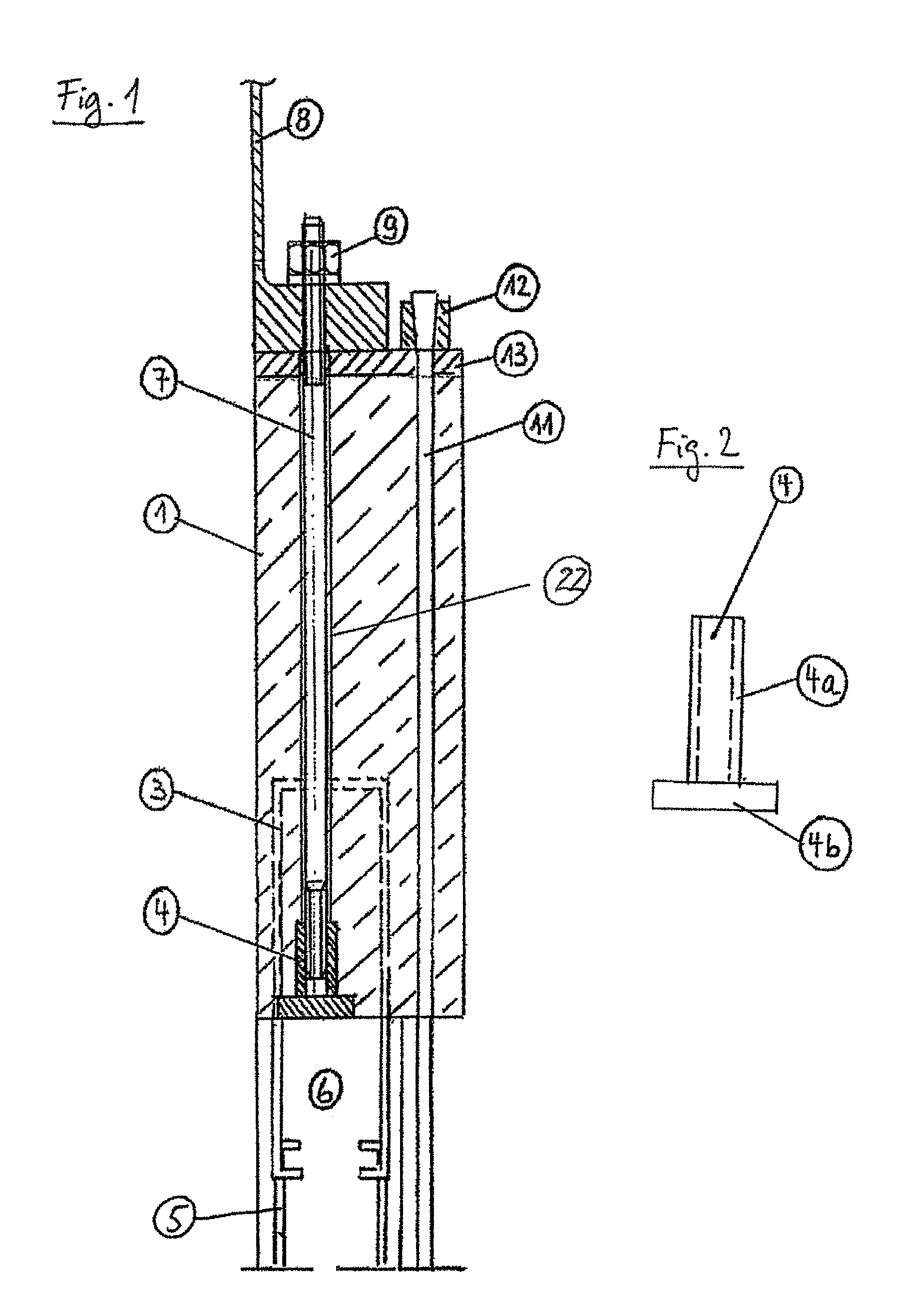
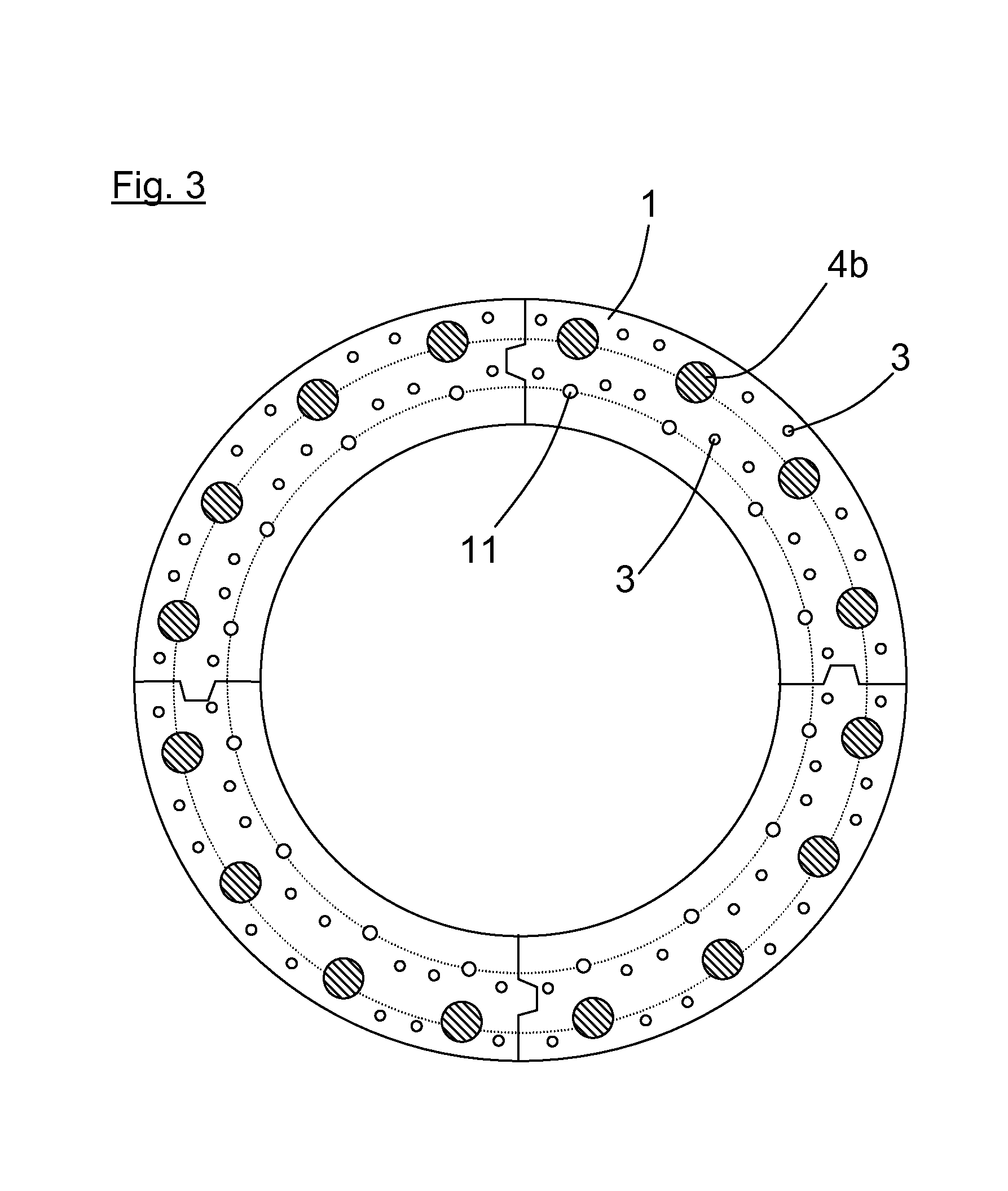
[0035]The anchoring assembly part 1 of FIG. 1 is prefabricated from a concrete material. It is a ring segment in the shape of a cylinder shell. A half or quarter shell can also be used.

[0036]The anchoring assembly part 1 has a plurality of bores for accommodating an anchor bolt 7, distributed uniformly over the perimeter and aligned in the axial direction. The bores extend over the entire height of the anchoring assembly part 1. An anchor sleeve 4 is arranged on the lower end of the anchoring assembly part. A disc, whose lower end is flush with the lower face of the concrete ring, forms the lower end of the anchor sleeve. Besides, the anchor sleeve 4 has an internally threaded...


PUM


Abstract

An anchoring assembly part for a wind turbine tower, which part is in a ring- or ring segment shape and prefabricated from a concrete material, and which has at least one projecting reinforcement element for the connection with a lower tower portion made of a concrete material, and at least one bore for receiving an anchor bolt for the detachable connection with an upper tower portion made of steel, an anchor sleeve with an internal thread for screwing in the anchor bolt being arranged in said bore.

Description

CROSS-REFERENCE TO RELATED APPLICATIONS[0001]Not applicable.STATEMENT REGARDING FEDERALLY SPONSORED RESEARCH[0002]Not applicable.BACKGROUND OF THE INVENTION[0003]The present invention is related to an anchoring assembly part for a wind turbine tower for connection with a lower tower portion, made of a concrete material, and with an upper tower portion made of steel.[0004]Wind turbine towers with tower portions from different materials are also called hybrid towers. The lower concrete-made tower portion is produced of a concrete material. Prefabricated concrete prefabs can be joined together on the construction site, or the concrete tower portion can be produced completely on the construction site by casting (in situ concrete). The steel-made tower portion can consist of plural tubular tower segments, wherein the individual tower segments are produced in one piece or joined together from plural elements that are distributed over the perimeter of the section.[0005]Particular difficult...

Claims


Application Information

Patent Timeline
Patent Type & Authority Patents(United States)
IPC IPC(8): E04H12/00
CPCE02D27/42F03D11/00F05B2260/301Y02E10/722F03D80/00Y02E10/728F03D13/20Y02E10/72
Inventor JAKUBOWSKI, ALEXANDER
Owner NORDEX ENERGY
Why Eureka
Try Eureka