Apparatus for determining breakage properties of particulate material

a technology of particulate material and breakage properties, which is applied in the direction of material strength using tensile/compressive force, instruments, grain treatment, etc., can solve the problems of low efficiency of mills in mineral processing industry, affecting the operation of plants, and breaking up rock bodies in crude fashion

Inactive Publication Date: 2012-09-25
THE UNIV OF QUEENSLAND
View PDF19 Cites 9 Cited by
  • Summary
  • Abstract
  • Description
  • Claims
  • Application Information

AI Technical Summary

Benefits of technology

[0051]The control of the impact velocity may be achieved by any suitable means. Preferably the control system, through the drive, includes means for controlling the circumferential or rotational speed of the rotor, most preferably with a high degree of accuracy. It will be appreciated that the speed of the rotor determines the amount of energy imparted to the particle. The control system also preferably provides a means for adjusting, preferably finely adjusting, the rotational speed of the rotor. This may be achieved by adjusting the amount of current supplied to the coil of the motor, for example through a variable frequency inverter, when the drive is an electric motor. This enables the rotor to be set at different speeds corresponding to different energy levels that may be imparted to test particles of the particulate material in use.
[0077]In alternative embodiments, the classifier is a non-mechanical classifier. For example, the classifier may be an optical classifier that advantageously enables quick and easy analysis of the particle size distribution of the broken particles by feeding them into the optical classifier. In this case, the analysis may be easily imaged onto a screen using appropriate software and considered, or saved for future reference.

Problems solved by technology

Blasting with explosives will break up the rock body in a rather crude fashion.
As a general proposition, mills in the mineral processing industry operate with a low level of efficiency.
Often the mills are operated crudely based on an operator's understanding of the mill and there is very little science in the operation of the plant.
Further the mill settings during operation of the mill are often not adjusted depending on the characteristics of the particles being processed by the mill at any one time.
At the bottom of the guide the weight collides with the test particle causing it to break.
This collision causes particle breakage.
A first major limitation is that the tests are conducted manually.
The process is not automated at all and carrying out tests is very time consuming.
Generally, the tests are carried out by a laboratory technician and the labour cost alone of carrying out the tests is substantial.
A further limitation of the drop weight test described above is that the smallest size of particle that can realistically and practically be tested by the apparatus is 10 mm in diameter.
It is very difficult and time consuming to try and mount a particle that is smaller than this on the rebound pendulum.
The problem with this is that a sizeable percentage of the particles that are fed into the mill in an operating plant are less than 10 mm in diameter.
Thus existing test procedures do not test particles of less than 10 mm and do not provide any insight into their breakage characteristics.
However, experiments conducted by the Applicant suggest that this assumption is not valid and particles that are less than 10 mm often break differently to the larger particles.
Firstly, there are high energy impacts.
Secondly, there is breakage due to repeated small energy impacts.
This procedure is very time-consuming and labour-extensive to quantify with the drop weight tester.
However, the reduced number of test particles will affect the statistical validity of the test results.

Method used


Image

  • Apparatus for determining breakage properties of particulate material
  • Apparatus for determining breakage properties of particulate material
  • Apparatus for determining breakage properties of particulate material

Examples


Embodiment Construction

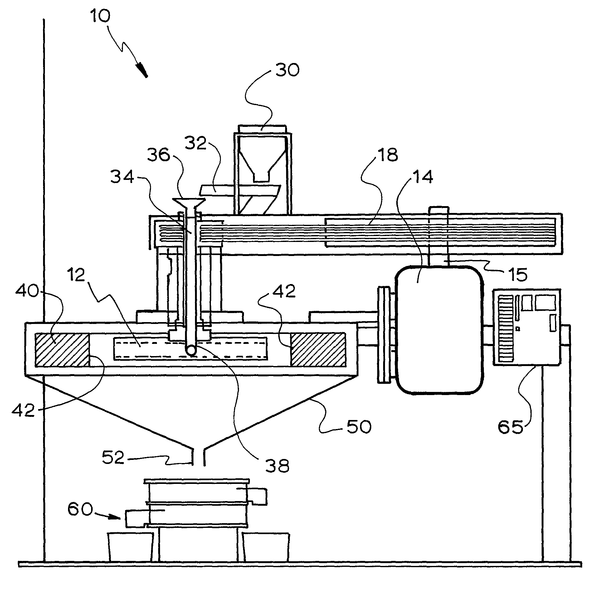
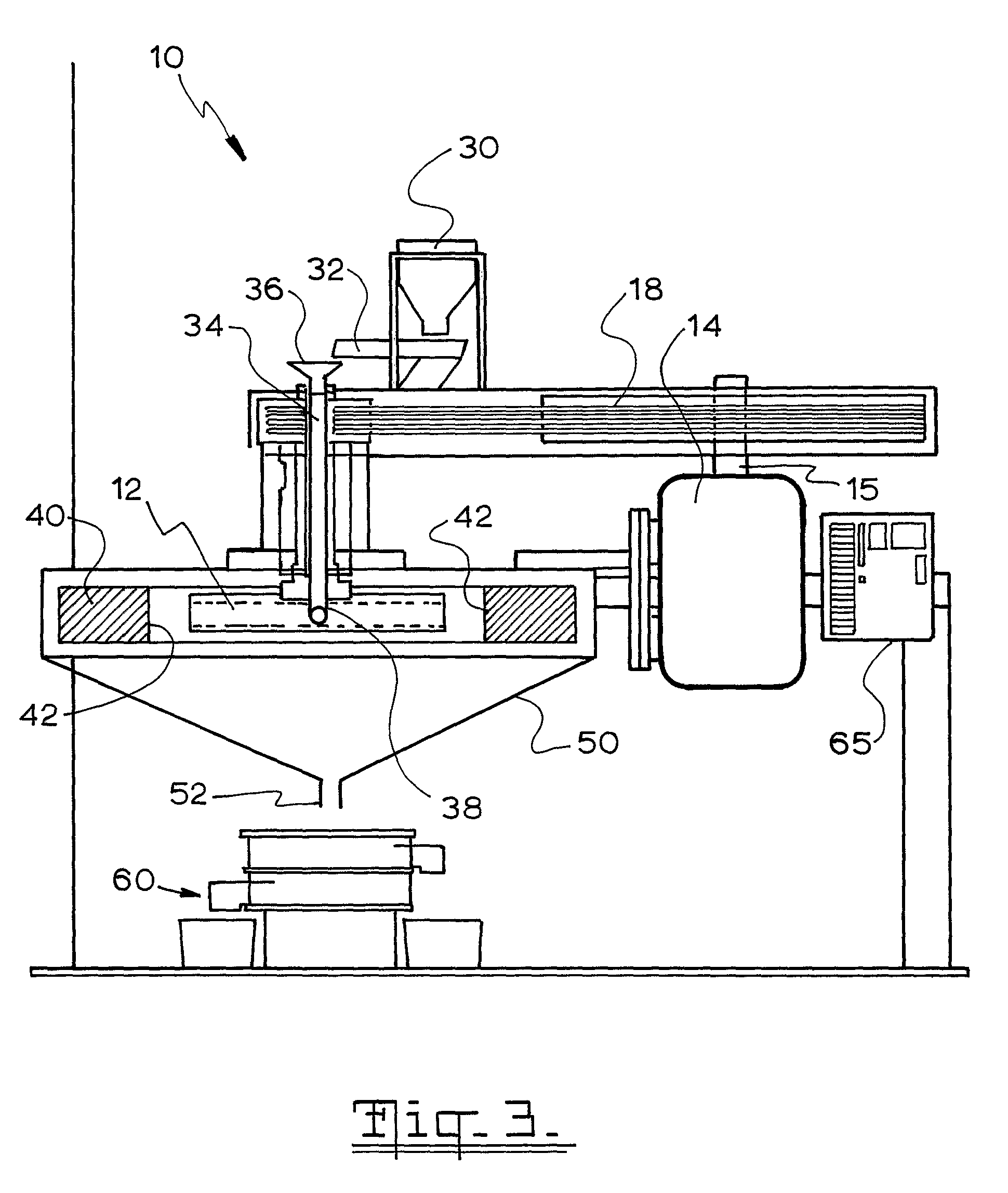
[0118]An apparatus and method for determining the breakage properties of particles in accordance with this invention may manifest itself in a variety of forms. It will be convenient to hereinafter provide a detailed description of one embodiment of the invention with reference to the accompanying drawings. The purpose of providing this detailed description is to instruct persons having an interest in the subject matter of the invention how to put the invention into practice. It is to be clearly understood however that the specific nature of this detailed description does not supersede the generality of the preceding statements. In the drawings:

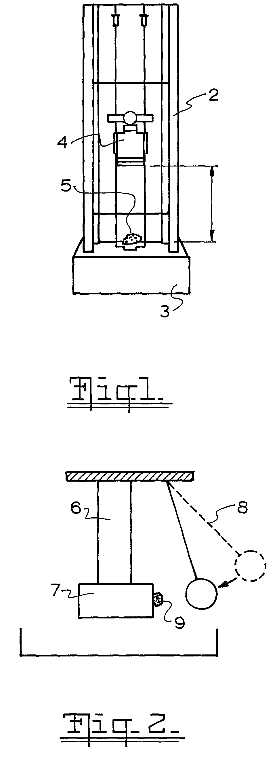
[0119]FIG. 1 is a schematic front view of an apparatus for characterising rock breakage that is known in the prior art;

[0120]FIG. 2 is a schematic side view of another prior art apparatus similar to that in FIG. 1 showing how the apparatus impacts the test particle to cause breakage thereof;

[0121]FIG. 3 is a schematic sectional front view of a...


PUM

PropertyMeasurementUnit
angleaaaaaaaaaa
diameteraaaaaaaaaa
diameteraaaaaaaaaa

Abstract

An apparatus for determining the breakage properties of a particulate material, the apparatus including: a support; a rotor mounted relative to the support and including at least one guide channel through which a particle of the particulate material is guided in use, the guide channel having an inlet and an outlet; a drive associated with the rotor; a feed channel for feeding particles of the particulate material to the inlet of the guide channel; a stator associated with the rotor and including an impact surface that is radially spaced from a circumferential edge of the rotor; and a collector for collecting pieces of the particulate material following impact; wherein the apparatus is provided with a control system for accurate control and adjustment of impact velocity of the particulate material with the impact surface.

Description

CROSS REFERENCE TO RELATED APPLICATIONS[0001]This application claims the priority benefit of PCT / AU2007 / 000631 filed on May 10, 2007 and Australian Application Nos. 2006902688 and 2006904417 filed May 18, 2006 and Aug. 15, 2006, respectively.FIELD OF THE INVENTION[0002]This invention relates to apparatus for determining the breakage properties of a particulate material. This invention also extends to a method for determining the breakage properties of a particulate material. Further, the invention extends to a method for determining the probability of breakage of a particulate material.[0003]This invention relates particularly but not exclusively to apparatus for quickly and efficiently determining the breakage characteristics or properties of test particles of a material, for example coal and mineral ore particles, both in a laboratory setting and also in a full scale mineral processing plant. It will therefore be convenient to hereinafter describe the invention with reference to t...

Claims


Application Information

Patent Timeline
Patent Type & Authority Patents(United States)
IPC IPC(8): G01N3/31
CPCB02C19/0025B02C25/00G01N3/565G01N3/48G01N2203/0234G01N2203/0087
Inventor KOJOVIC, TONILARBI-BRAM, STEPHENSHI, FENGNIANMANLAPIG, EMMANUEL
Owner THE UNIV OF QUEENSLAND
Why Eureka
Try Eureka