Micropower passive electronic lock cylinder

a passive electronic lock and micro-power technology, applied in the field of electronic locks, can solve the problems of high power consumption, large number of batteries of active electronic locks, and electronic locks using commercial power for power supply, and achieve the effects of low power consumption, high safety, and high conversion efficiency

Inactive Publication Date: 2012-10-02
LUO SHIFU
View PDF14 Cites 27 Cited by
  • Summary
  • Abstract
  • Description
  • Claims
  • Application Information

AI Technical Summary

Benefits of technology

[0014]1. A stepping micromotor or a rotary solenoid (also known as rotary electromagnet, whose basic operating principle is equivalent to that of the stepping micromotor but has simpler structure) is used as an executive element to drive an unloaded displacement limiting cam. The electromechanical conversion efficiency of this technical solution is much higher than that of the technical solution using a linear solenoid to drive a loaded (compression spring) plunger, and the driving current is smaller. The power-on time for locking or unlocking occurs in tens of milliseconds, so that the operating power consumption is lower than that of a lock using a linear solenoid by more than one order of magnitude. This means that when using a battery with the same capacity, the number of unlocking cycles (and thus battery life) of the micropower passive electronic lock cylinder is significantly greater than that of a lock cylinder adopting a linear solenoid, and the power consumption for locking and unlocking is relatively low. Therefore, batteries of smaller volume and capacity can be used for the micropower passive electronic lock cylinder so as to adapt to the modern trends of economy, small size, light weight, small thickness and protection of the environment.
[0015]2. The displacement limiting cam on the shaft of the micromotor has automatic identifying, locating and self-locking functions, so the position of the displacement limiting cam cannot be changed after power-off, and the lock plug can rotate arbitrarily for several circles without any power consumption.
[0016]3. The micropower passive electronic lock cylinder does not comprise a part equivalent to a linear solenoid plunger which can move axially under inertia. Therefore, the lock cylinder cannot be mistakenly unlocked under an impact force from any direction.
[0017]4. The microcontroller unit in the electronic lock plug can detect the dynamic and static positions of the displacement limiting cam and the lock pin, relative to the surrounding environment. Therefore, the invention provides a new electronic lock cylinder which can be adapted for connection to a wired / wireless communication network for functions of real-time remote monitoring and the like, thereby broadening the application range of the invention.
[0018]5. The electronic lock plug has the advantages of high commercial viability, easy size standardization, fewer mechanical parts and components, compact structure and small size, and can be easily fitted into various traditional immovable cylinder bodies of various external dimensions to produce an independent passive electronic lock cylinder. The invention can be used to directly substitute, replace or upgrade a mechanical lock cylinder of a traditional mechanical lock, and form serial products of passive electronic locks.

Problems solved by technology

Therefore, the active electronic lock not only consumes a large number of batteries, but also requires more maintenance work, such as frequent inspection, battery replacement and the like.
Furthermore, the batteries may be in loose contact such that electronic elements and devices become aged from being energized for long, influencing the reliability and service life of the active electronic lock.
On the other hand, electronic locks making use of commercial power for power supply have disadvantages of a limited application range, high power consumption in standby state all the year round, inconvenient installation, increased maintenance, and adverse effects on protection of the environment.
However, the above-mentioned patented technological packages cannot be used for to develop a passive electronic lock cylinder that is as small as a common mechanical lock cylinder to directly substitute or replace the mechanical lock cylinder.
1. The passive electronic lock cylinder uses a linear solenoid as an executive element, and the plunger (a displacement limiting armature for locking and unlocking) of the linear solenoid does not have locating and self-locking functions after power-off (namely that the plunger is automatically restored by a compression spring as soon as power is switched off). The linear electromagnetic solenoid must therefore be energized to attract the plunger. The power-on time for unlocking (namely the waiting time for rotating a lock plug to a specified angle via the key) is about 1 second; resulting in increased electric energy being consumed during this time, and the electromechanical conversion efficiency of the passive electronic lock cylinder is low. A battery with relatively large volume and capacity must be installed in the active electronic key to provide for extended use over time, making the size of the active electronic key relatively large.
2. The plunger does not have a self-locking function after power-off, so that the rotation angle of the lock plug cannot be more than 360 degrees (by comparison the lock plug of a common lock cylinder for an anti-theft door is required to rotate more than 720 degrees). If the lock plug is required to rotate several times, it consumes substantially more electric energy, decreasing the usefulness and commercial viability of the lock.
3. The microcontroller unit (MCU) in the electronic control circuit of the lock plug cannot distinguish between the dynamic and static mechanical positions of the pin and plunger in the lock plug, and therefore cannot distinguish between the locking and unlocking states of the lock cylinder. Therefore, the passive electronic lock cylinder cannot be adapted to perform remote monitoring functions and the like, or functions requiring higher intellectualization and higher safety through wired / wireless networks.
The cylinder of the intellectual passive electronic lock disclosed has the disadvantages of: being unable to distinguish between the dynamic and static positions of mechanical actuating elements due to the adoption of the linear electromagnetic solenoid (electromagnet) as an executive element.
Furthermore, the intellectual passive electronic lock cylinder also has the three disadvantages of the patent ZL 01804076.4; in that there is no disclosure of measures taken to prevent unexpected unlocking caused by the impact of external force, so that when exerting an impact force on the lock cylinder, a driving rack will move axially, under inertia engaging with a driven rack.

Method used


Image

  • Micropower passive electronic lock cylinder
  • Micropower passive electronic lock cylinder
  • Micropower passive electronic lock cylinder

Examples


Embodiment Construction

[0036]The invention will further be described with reference to the figures and specific embodiments.

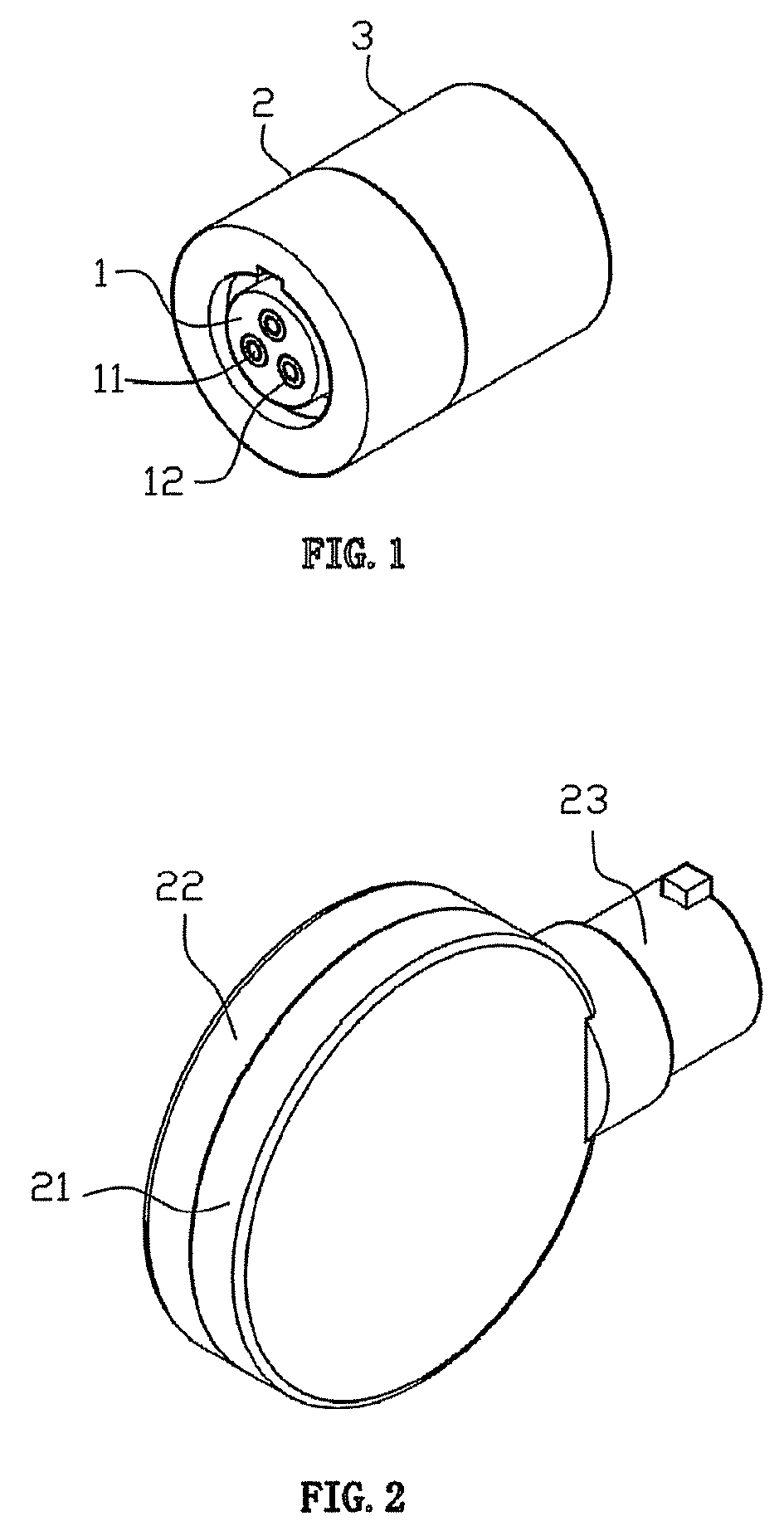
[0037]FIG. 1 shows a perspective view of the lock cylinder in which a typical cylindrical electronic lock cylinder comprises a rotatable plug 1, a front cover 2 and a cylinder body 3, wherein the front cover 2 and the cylinder body 3 can be assembled by processes such as interference fit, cohering, soldering, and the like. Three contact electrodes 11 and an insulating bush 12 are located in the rotatable plug 1. When the lock cylinder is matched with different types of mechanical locks, the shape and structure of the front cover and the cylinder body can be correspondingly adapted. The front cover and the cylinder body can thus be adapted to fit various types of mechanical locks, and fitted in similar fashion to that of common traditional mechanical lock cylinders.

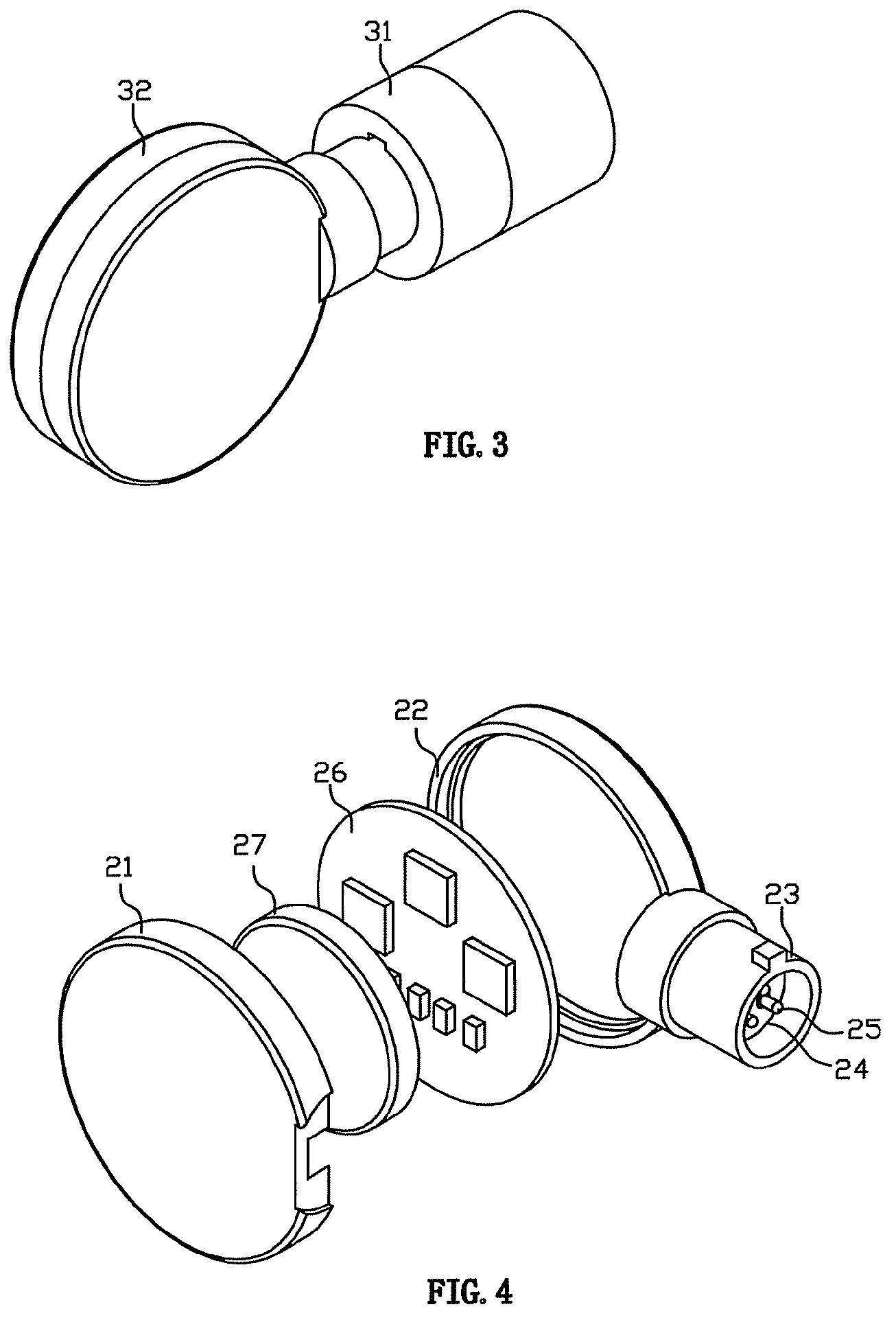
[0038]FIG. 2 shows the perspective view of the key in which the outward appearance of an electronic key is formed by comb...


PUM


Abstract

A micropower passive electronic lock cylinder including an immovable cylinder body (3), a rotatable plug (1), and an electronic control circuit part is described. An electronic control circuit board (13) electrically connected with a micromotor (14) and locating switches (15, 16) is arranged in the rotatable plug (1). A lock pin (8), which is controlled by a displacement limiting cam (5) driven by the micromotor (14), moves between the immovable cylinder body (3) and the rotatable plug (1) to release or block the rotatable plug (1).

Description

TECHNICAL FIELD[0001]The invention relates to the field of electronic locks.BACKGROUND[0002]An electronic lock using commercial power or batteries, which is directly connected with the circuit in the lock body to supply power, is called an “active electronic lock”. Traditional active electronic locks (adopting IC card, ID card, fingerprint identification and the like) that are widely used at present need 4 to 6 pieces of batteries of size AA or LR6, and the service life of the batteries is usually 3 to 12 months. Therefore, the active electronic lock not only consumes a large number of batteries, but also requires more maintenance work, such as frequent inspection, battery replacement and the like. Furthermore, the batteries may be in loose contact such that electronic elements and devices become aged from being energized for long, influencing the reliability and service life of the active electronic lock. On the other hand, electronic locks making use of commercial power for power ...

Claims


Application Information

Patent Timeline
Patent Type & Authority Patents(United States)
IPC IPC(8): E05B49/00
CPCE05B47/063E05B47/0005E05B2047/0024E05B47/0012Y10T70/5978Y10T70/7073Y10T70/5973Y10T70/7102Y10T70/7068Y10T70/7136Y10T70/7079Y10T70/713
Inventor LUO, SHIFU
Owner LUO SHIFU
Why Eureka
Try Eureka