Transmission of vehicle-relevant data of a vehicle via mobile communication

a vehicle and mobile communication technology, applied in the field of communication and safety technology for vehicles, can solve the problems of limited junction assistance function, inability to inability to achieve direct communication between vehicles at junctions, so as to improve communication between vehicles

Active Publication Date: 2012-10-02
CONTINENTAL TEVES AG & CO OHG
View PDF11 Cites 31 Cited by
  • Summary
  • Abstract
  • Description
  • Claims
  • Application Information

AI Technical Summary

Benefits of technology

[0010]The use of two communication units allows important, limited information to be transmitted via the second communication unit, so that there is the assurance that this information actually arrives at the receiver. The remaining data can be transmitted via the first communication unit—possibly with a higher bandwidth but a shorter range. The effect which may be achieved by this is that the most important data reach the receiver regardless of the ambient conditions for the vehicles.
[0011]The use of already existing communication technologies for the second communication unit (but also for the first communication unit) allows the problem of shadowing by buildings, etc., to be overcome very easily and inexpensively. The demands of WLAN-based communication are not affected in this case.
[0016]In this way, the transmission range of the second data can be increased if the radio transmission link is blocked by obstacles.
[0021]In this way, the data traffic can be adapted individually and hence reduced.
[0023]In line with a further exemplary embodiment of the invention, the first data and the second data are transmitted in the same format. This makes it possible to ensure that a terminal is also able to read the second data if it can read the first data (and vice versa).

Problems solved by technology

Unfortunately, radio waves in this frequency range are absorbed by houses, shrubs, parking cars, etc., in exactly the same way as visible light.
For this reason, direct communication between the vehicles at a junction does not become possible until the vehicles are in visual contact with one another, as a result of which the benefit of C2X communication for the junction assistance function is limited.

Method used


Image

  • Transmission of vehicle-relevant data of a vehicle via mobile communication
  • Transmission of vehicle-relevant data of a vehicle via mobile communication
  • Transmission of vehicle-relevant data of a vehicle via mobile communication

Examples


first exemplary embodiments

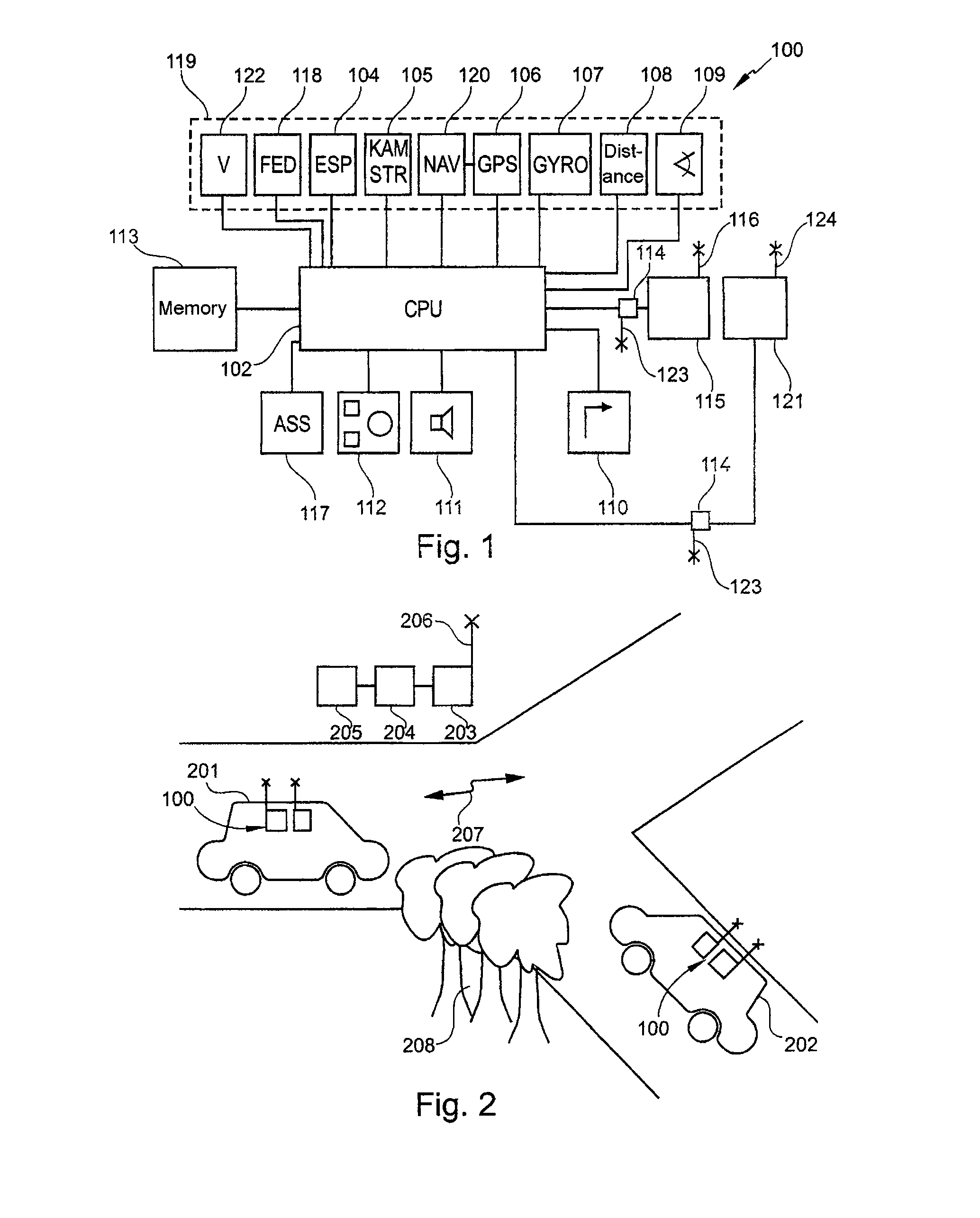
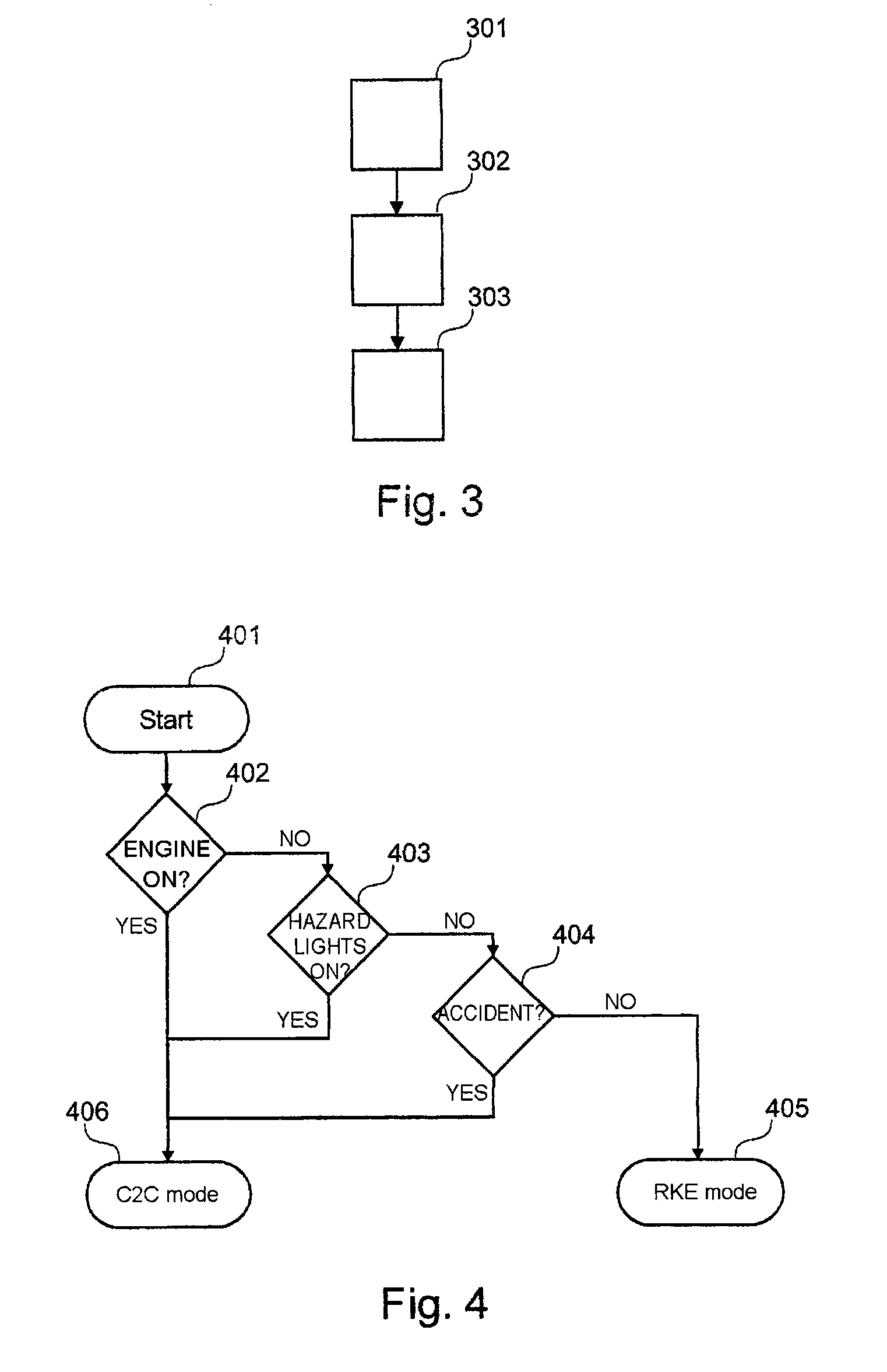
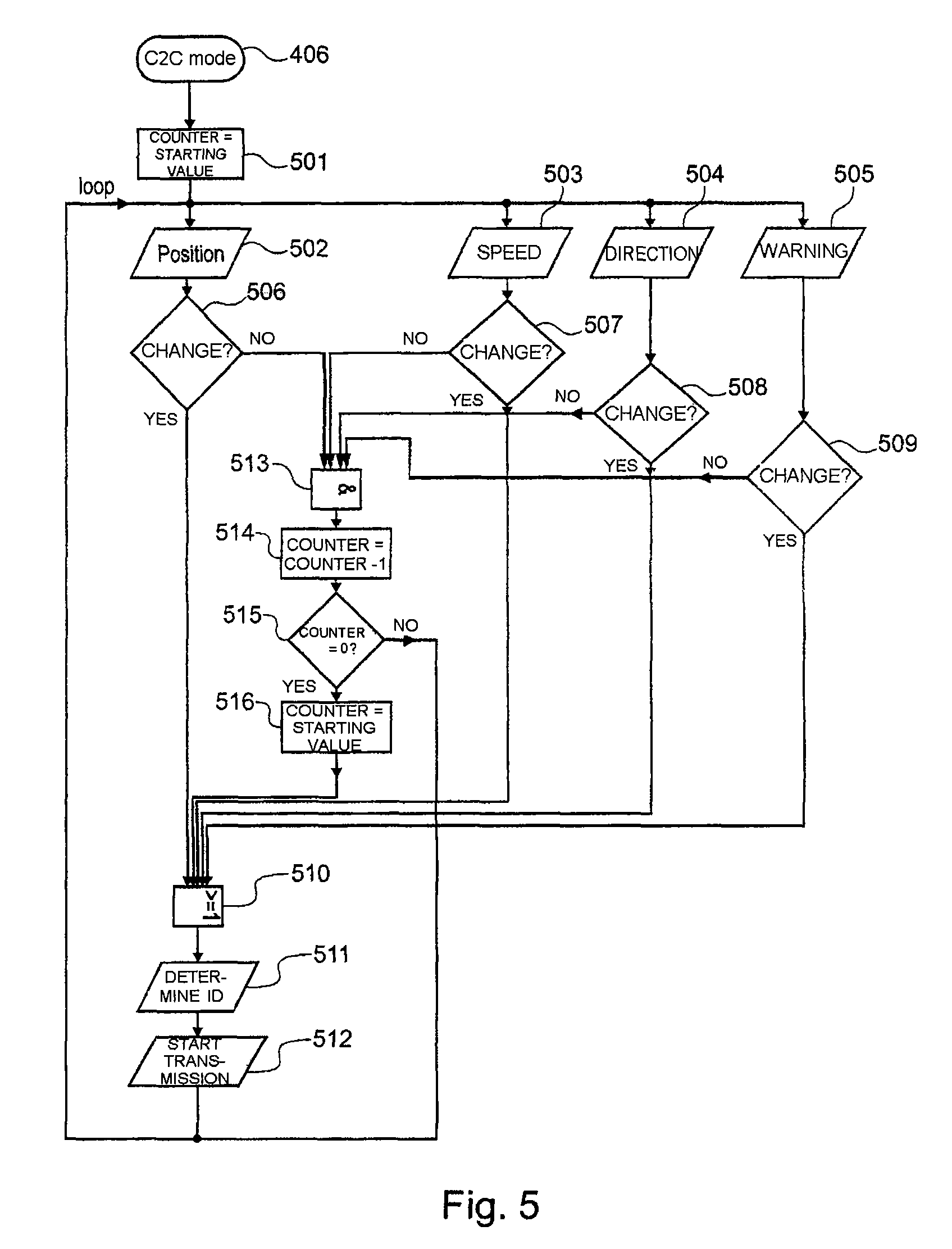
[0088]FIG. 4 and FIG. 5 show flowcharts for methods based on exemplary embodiments of the invention to illustrate the coexistence C2X, RKE or the use of two communication units.

[0089]The coexistence or the processing of both instances of application (C2X and RKE) as an integration step will first of all be illustrated by way of example with reference to FIG. 4. Following once-only initialization [starting] of the radio communication controller in step 401, the vehicle status is requested [in step 402, a check is performed to determine whether the engine is switched on; in step 403, a check is performed to determine whether the hazard lights are switched on; in step 404, a check is performed to determine whether an accident sensor has responded, that is to say whether an accident has been detected] and then the decision-making is performed for the respective mode [C2C mode, RKE mode]. If one of these questions receives a yes response, the system operates in C2C mode. If all these que...

second exemplary embodiments

[0105]The methods and systems already described can be used to support or extend vehicle-to-vehicle X communication (C2X) by means of the radio technology of wireless access and driving authorization units.

[0106]This involves setting up a radio link at 433 MHz or 800 MHz to 980 MHz (driving authorization communication) in addition to the intended 5.9 GHz (DSRC) in order to use better physical properties of said radio link.

[0107]The second exemplary embodiment described below further improves the invention in the area of prioritization and congestion control.

[0108]To date, it has been proposed that CSMA be used for congestion control in the driving authorization communication. This is now being extended. If communication by means of DSRC already exists in a parameter around the vehicle, driving authorization communication is no longer used for transmission. This ensures that in areas with a relatively large density of vehicles the low frequency is not overloaded and is free for other...

fourth exemplary embodiments

[0135]Road traffic accidents with pedestrians often occur in confusing situations or because the driver of the motor vehicle has merely not seen the pedestrian. For this reason, intensive development is currently being put into pedestrian recognition by means of video sensor systems. However, these have the same problem as the driver, in principle, that they can only recognize pedestrians who are visible in visual terms from the vehicle.

[0136]This is the starting point for the fourth exemplary embodiments. Many modern vehicles are equipped with a “remote keyless entry” function, that is to say with a radio key. Modern versions of these radio keys have a range of 100 m and more. Many pedestrians have vehicles and therefore also have a radio key with them.

[0137]This is subsequently used in order to recognize these pedestrians. To this end, the driving authorization unit in the vehicle transmits a “search command” at short intervals while traveling. If a key receives such a search comm...


PUM


Abstract

A device, method, computer program and computer readable medium allowing for vehicle to vehicle and vehicle to infrastructure communication. An ignition key radio technology may used in addition to WLAN-based communication in a vehicle in order to communicate with other vehicles or infrastructure. The ignition key radio technology is used to send only selected data which have been altered significantly. The remaining data are not sent or kept for the WLAN communication.

Description

CROSS REFERENCE TO RELATED APPLICATIONS[0001]This application is the U.S. national phase application of PCT International Phase Application No. PCT / EP2008 / 067344, filed Dec. 11, 2008, which claims priority to German Patent application No. 10 2007 059 829.9, filed Dec. 11, 2007, and also German Patent applications No. 10 2008 009 331.9, filed Feb. 14, 2008, No. 10 2008 011 196.1, filed Feb. 26, 2008, No. 10 2008 021 723.9, filed Apr. 30, 2008, No. 10 2008 021 725.5, filed Apr. 30, 2008, No. 10 2008 021 780.8, filed Apr. 30, 2008, No. 10 2008 041 979.6, filed Sep. 10, 2008, No. 10 2008 043 010.2, filed Oct. 21, 2008, No. 10 2008 043 080.3, filed Oct. 22, 2008, No. 10 2008 043 081.1, filed Oct. 22, 2008, No. 10 2008 043 050.1, filed Oct. 22, 2008, No. 10 2008 043 075.7, filed Oct. 22, 2008, the contents of such applications being incorporated by reference herein.FIELD OF THE INVENTION[0002]The invention relates to communication and safety technology for vehicles. In particular, the inv...

Claims


Application Information

Patent Timeline
Patent Type & Authority Patents(United States)
IPC IPC(8): G06F7/00
CPCH04L67/12G08G1/161B60W2556/65
Inventor STAHLIN, ULRICHMENZEL, MARCBAIER, ROBERTERDEM, BETTINAWILLNECKER, THOMASGEE, ROBERTMOLLER, ULRICHSCHAFER, MAIKBAUER, OLEGAUNKOFER, MARKUS
Owner CONTINENTAL TEVES AG & CO OHG
Why Eureka
Try Eureka