
Distiller grain pellet production devices

a technology of production device and distillation machine, which is applied in the direction of butter production, drying solid materials, drying machines, etc., can solve the problems of inability to extend inability to prolong the storage life of wet grains, and inability to prolong the storage life of dry grains

Active Publication Date: 2012-10-16
JOHNSON RAYMOND T +1
View PDF25 Cites 33 Cited by
  • Summary
  • Abstract
  • Description
  • Claims
  • Application Information

AI Technical Summary

Benefits of technology

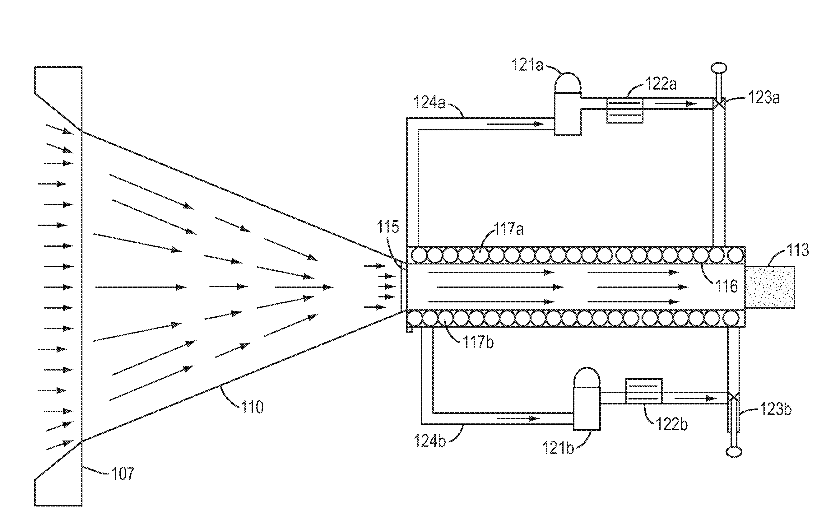
[0010]It is the object of the invention to provide a livestock feed material in the form of distiller dried grains without the addition of additives and / or supplements by producing a pelletized livestock product that has high shipping durability, high quality, and high nutritional value. Thus, the final product provides optimum nutritional value in a very compact and efficient form.
[0013]It is a further object of the invention to produce, from distiller grain, a product such as a pellet or cube, which is sufficiently dense to endure being augured several times during transport without breaking apart and becoming damaged. The density of the pellets or cubes is manipulated and controlled during the production process such it prevents the final product from crumbling or falling apart.
[0014]It is another object of the invention to provide a high-protein and fat product, without additives, that can be spread onto the ground as livestock feed and is capable of enduring various weather conditions.
[0015]It is another object of the invention to provide a method, which does not require heating or curing of the pellets after the pellets are produced.

Problems solved by technology

However, one of the major problems with wet distiller grains is that it is susceptible to mold and mildew when exposed to air for about 4 to 5 days.
This potential mold and mildew issue makes it imperative that the wet grains are used and consumed relatively quickly, because extended storage of wet grains is not feasible.
Dried grains therefore have longer storage life.
While dried grains have several advantages over wet grains, they do have some properties that make them less than desirable as a livestock feed.
First, the dried grains have a loose and granular consistency which makes them susceptible to dilution and spoilage when spread on the ground as feed and exposed to the weather.
In this loose granular form, the livestock consuming the dried grains do not receive the full potential benefit of the nutritional value of the feed, because of the relatively low density of the material.
Second, transportation of loose granular material such as dried grains also presents material handling issues when compared to more dense bulk material.
Given that the drying process generally takes place in a rotating drum with an open boundary between the grain and the heated combustion gases, there is a constant danger of potential explosions within the volatile atmosphere inside the drying drum.
This problem can be a major safety hazard for personnel operating the dryers and it can cause down time and increased capital cost.
While this solution is an improvement over the loose granular dried grains, the addition of supplements to the dried grains results in an increase in cost and lowers the nutritional value per unit volume of the final product in comparison to a dried grain pellet produced without such binders and supplements.
One of the main problems with the pellets and cubes produced from this conventional technique is that they are made with binders and fillers, to keep them together.
Some of the conventional pellet producing methods require a heating or curing process applied to the pellet or cube after it is formed in order to boil off the corn oil, which also lowers the protein level.
This repeated stress can cause the product to break apart or become damaged.

Method used


Image

  • Distiller grain pellet production devices
  • Distiller grain pellet production devices
  • Distiller grain pellet production devices

Examples


Embodiment Construction

[0031]Reference will now be made to various embodiments, examples of which are illustrated in the accompanying drawings. However, these various exemplary embodiments are not intended to limit the disclosure. On the contrary, the disclosure is intended to cover alternatives, modifications, and equivalents.

[0032]Throughout the application, description of various embodiments may use “comprising” language; however, it will be understood by one of skill in the art, that in some specific instances, an embodiment can alternatively be described using the language “consisting essentially of” or “consisting of.”

[0033]For purposes of better understanding the present teachings and in no way limiting the scope of the teachings, it will be clear to one of skill the art that the use of the singular includes the plural unless specifically stated otherwise. Therefore, the terms “a,”“an” and “at least one” are used interchangeably in this application.

[0034]Unless otherwise indicated, all numbers expr...


PUM

PropertyMeasurementUnit
Temperatureaaaaaaaaaa
Pressureaaaaaaaaaa
Lengthaaaaaaaaaa

Abstract

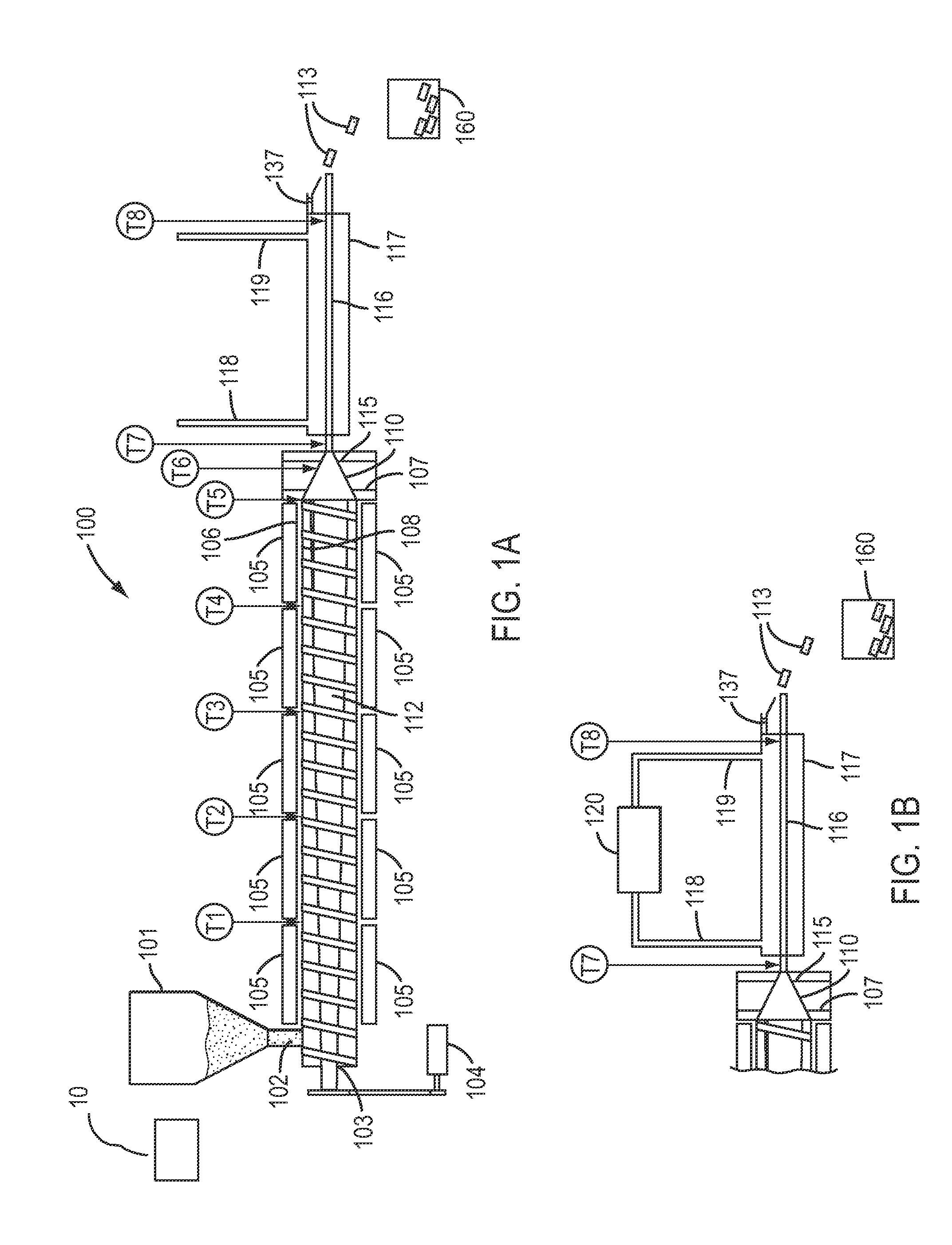
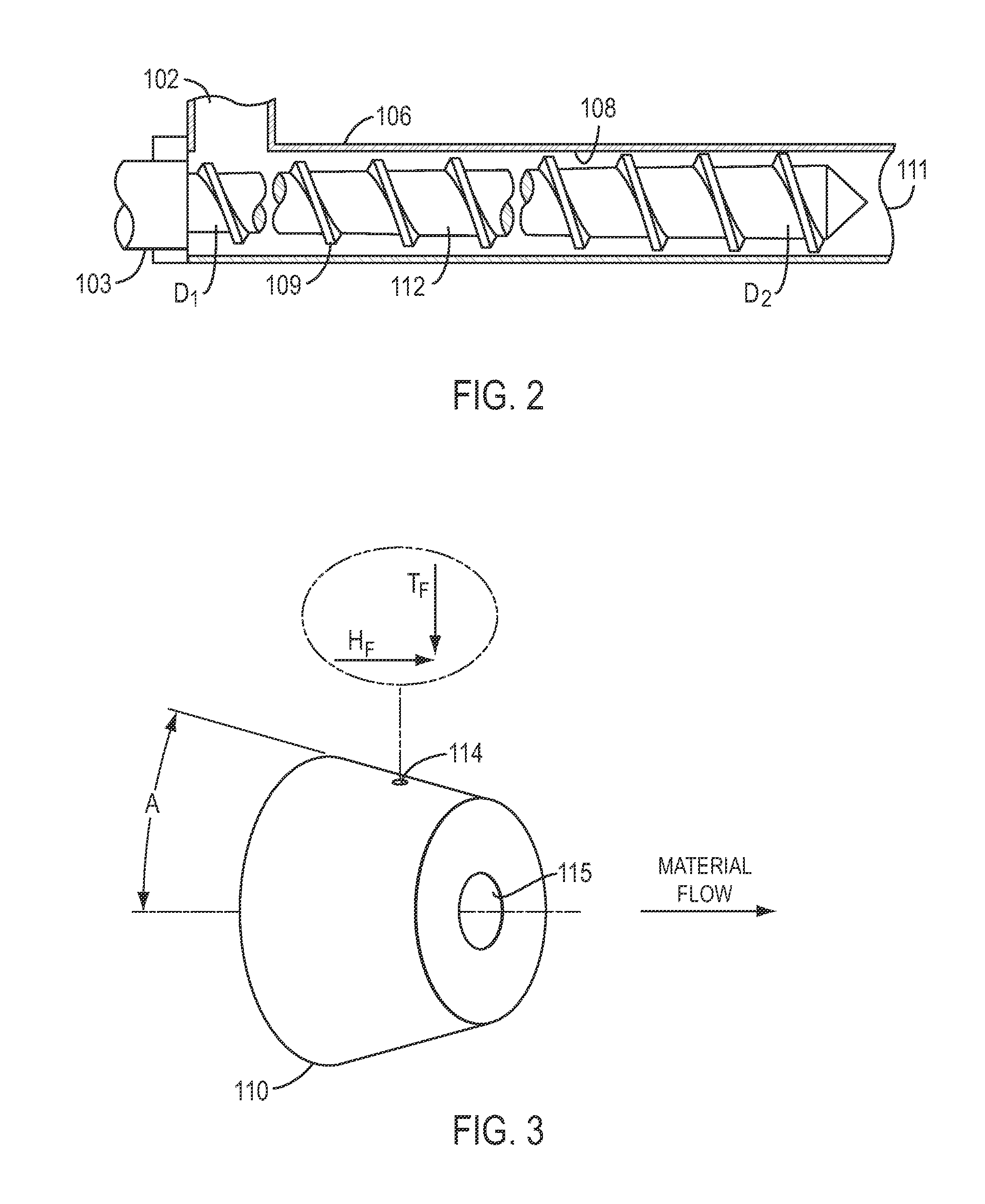
A device for producing a high density compact livestock feed from a loose granular material according to various embodiment can include a source for supplying a loose granular material to be treated. A series of successive treatment zones comprises a heating zone, a compression zone, and a cooling zone. The heating zone comprises at least one heater and at least one screw compression dryer configured to receive the loose granular material to be treated for drying. Rotation of the screw transfers the treated material to the compression zone. The compression zone comprises a compression chamber for compacting the treated material to form a high density compact body. The treated material is pressed through the compression chamber while a two-dimensional cross-section compression is applied to the treated material. The cooling zone comprises a cooling unit for cooling the high density compact body received from the compression zone.

Description

REFERENCE TO RELATED APPLICATION[0001]This application claims priority of U.S. Provisional Patent Application Ser. No. 61 / 476,224, which was filed on Apr. 15, 2011. The subject matter of the earlier filed application is hereby incorporated by reference.FIELD OF THE INVENTION[0002]This invention relates to an apparatus and method for treating granular material such as dry distiller grains (DDG) for the purpose of transforming the granular loose material into a dense cohesive bulk product and optionally extracting and collecting liquids and vapors from the bulk material as a separate product.BACKGROUND OF THE INVENTION[0003]In the field of animal feed processing, wet and dried distiller grains are a major feed source for farm livestock. This is due in part to the increased commercial interest in ethanol production. Wet distiller grains are one of the residual products of grain fermentation that forms during the production of ethanol. This residue, which is sometimes called mash, has r...

Claims


Application Information

Patent Timeline
IPC IPC(8): B29C47/92B29C47/78A23K10/38B29C48/04B29C48/05B29C48/30B29C48/32B29C48/345B29C48/395B29C48/90B29C48/92
CPCB29C47/92B29C47/6018A23P1/027B29C47/30B29C47/8815B29C2947/92638B29C47/0016F26B5/14F26B17/20A23K10/38A23P10/20A23P10/28A23P30/20B29C48/04B29C48/09B29C48/53B29C48/90B29C48/92B29C48/345B29C48/395B29C48/872B29C48/875B29C48/911B29C48/06B29C48/32B29C48/402B29C48/904B29C48/919B29C48/9135B29C2948/92B29C2948/926B29C2948/9259B29C2948/92019B29C2948/92209B29C2948/92428B29C2948/92638B29C2948/92704B29C2948/92923A23P10/25A23N17/005B29C48/05
Inventor THOMAS, MICHAEL R.
Owner JOHNSON RAYMOND T
Learn More