Self-referenced optical fiber sensor and related sensor network

a self-referenced, optical fiber technology, applied in the field of fiberoptic sensors, can solve the problem of still complex proposed architectures

Inactive Publication Date: 2012-10-16
THALES SA
View PDF18 Cites 18 Cited by
  • Summary
  • Abstract
  • Description
  • Claims
  • Application Information

AI Technical Summary

Benefits of technology

[0020]In addition, the sensor may have a structure substantially in the form of a cylinder around which the measurement optical fiber is wound, said cylinder being made of a material having the lowest possible Young's modulus so as to amplify the strain exerted on the fiber, the material of the cylinder being, for example, polydimethylsiloxane.

Problems solved by technology

However, the proposed architectures are still complex.

Method used


Image

  • Self-referenced optical fiber sensor and related sensor network
  • Self-referenced optical fiber sensor and related sensor network
  • Self-referenced optical fiber sensor and related sensor network

Examples


first embodiment

[0048]There are various methods for generating the two optical frequencies ν1(ε) and ν2(ε). A first embodiment is derived from that described in French patent application entitled “Capteur de grandeurs physiques à fibre optique insensible aux grandeurs statiques [Fiber-optic sensor for detecting physical quantities but insensitive to static quantities]” filed under number FR 07 / 01454.

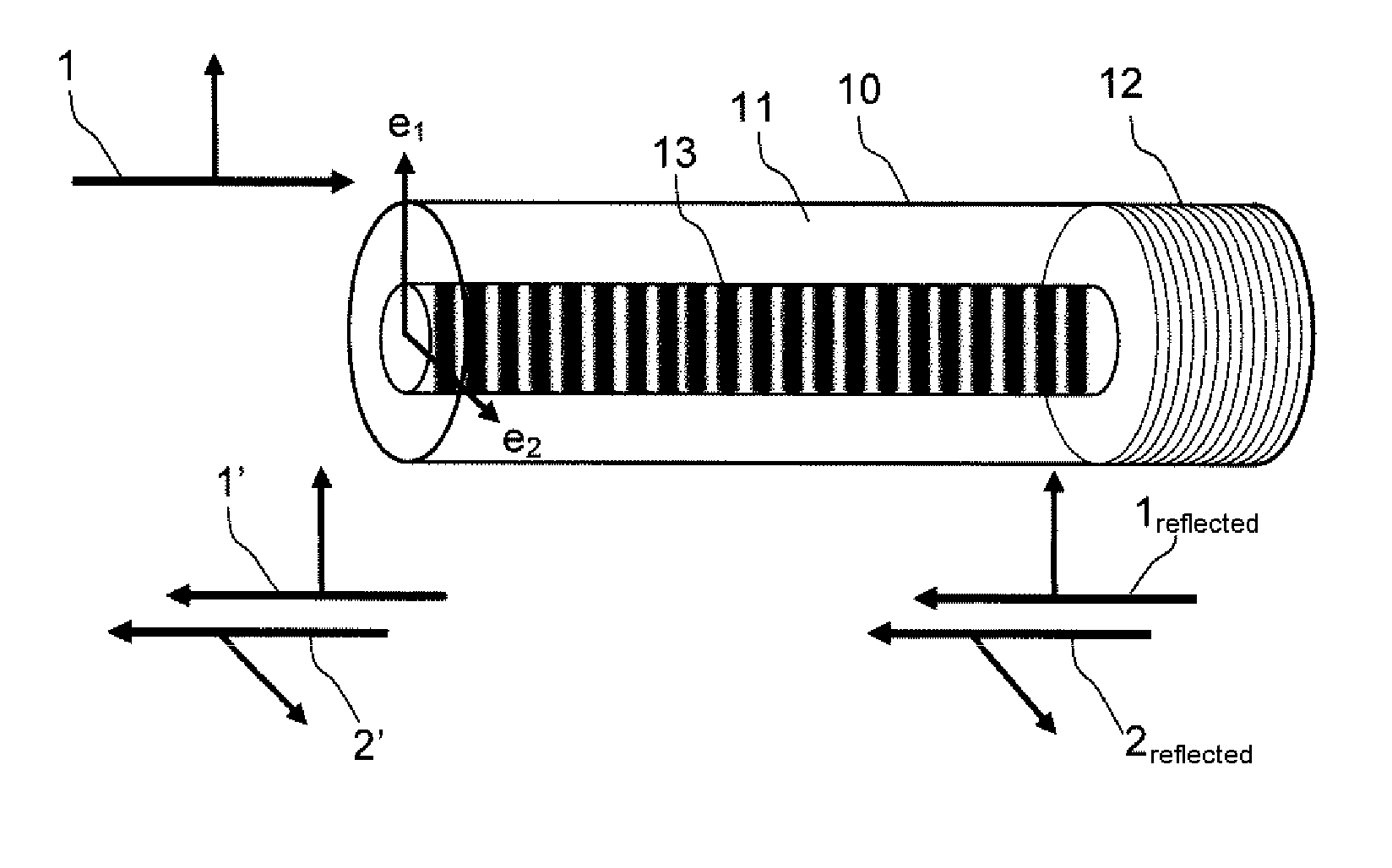
[0049]The basic principle of the physical process of mixing two waves in an amplifying medium, as described in the above application, is the following: the sensor comprises a doped optical fiber optically pumped beforehand so as to achieve population inversion between its energy levels. The fiber includes a Bragg mirror. If what is called a “probe” wave at an optical frequency:

[0050]ν1=cλ1

(in which C and λ1 represent the velocity of light and the wavelength in vacuum respectively) and of coherence length Lcoh at least equal to the length L of the fiber is injected, this wave is reflected on the Bragg mi...

second embodiment

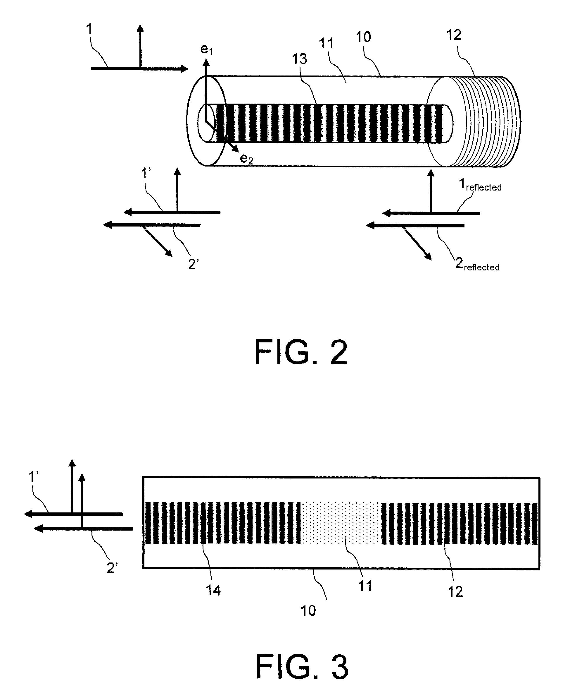
[0072]a sensor according to the invention is based on the use of DBR lasers. One view of the fiber employing this second principle is shown in FIG. 3. To produce sensors, DFB lasers are generally used. Their use for this type of application (in particular for hydrophones) is currently expanding rapidly. DFB lasers consist of a continuous Bragg grating etched in an optical fiber amplifier, typically doped with erbium or erbium-ytterbium. They are preferred to DBR fiber lasers, formed from two Bragg gratings 12 and 14 separated by a short length 11 of a few 100 μm of fiber amplifier. This is because, in DBR geometry, the distance between the two Bragg gratings allows the oscillation of several cavity modes lying within the reflection band of the gratings. This multimodal aspect has proved to be deleterious in most hydrophone applications. However, this multimodal aspect has certain advantages in the context of the sensors according to the invention.

[0073]This is because if the fiber c...


PUM

PropertyMeasurementUnit
wavelengthaaaaaaaaaa

Abstract

The general field of the invention is that of fiber-optic sensors comprising at least one measurement optical fiber having an optically pumped doped amplifying medium, the optical characteristics of which are sensitive to a physical quantity, the fiber having at least one Bragg grating. The fiber is designed so as to generate, in the amplifying medium, two optical waves having different optical frequencies that propagate in the same direction after reflection on the Bragg grating and are emitted by the amplifying medium, the two optical frequencies depending on the physical quantity. The two waves may be generated using either a birefringent polarization-maintaining fiber or a DBR (Distributed Bragg Reflector) laser cavity. Notably, this sensor may be used as a hydrophone.

Description

CROSS-REFERENCE TO RELATED APPLICATIONS[0001]This application is a National Stage of International patent application PCT / EP2009 / 053100, filed on Mar. 16, 2009, which claims priority to foreign French patent application No. FR 08 01482, filed on Mar. 18, 2008, the disclosures of which are incorporated by reference in their entirety.FIELD OF THE INVENTION[0002]The field of the invention is that of fiber-optic sensors for measuring physical quantities. Sensors based on optical fibers have been studied for almost thirty years. On this subject, the reader may refer, for example, to the publication by C. Menadier, C. Kissenger and H. Adkins entitled “The photonic sensor”, Instrum. Control Syst. Vol. 40, 114 (1967). They benefit from the advantages of optical fibers which, apart from their low weight, compact size, cost and insensitivity to electromagnetic interference, have low loss, have a high bandwidth and are suitable for multiplexing techniques and for the use of distributed amplifi...

Claims


Application Information

Patent Timeline
Patent Type & Authority Patents(United States)
IPC IPC(8): G02B6/00G01B11/16G01V1/18H04J14/02G01J1/04G01D5/353
CPCG01D5/35303G01L1/246H01S3/0007H01S3/06712H01S3/0675H01S3/0809H01S3/10H01S3/1053H01S3/1067G01D5/35312G01D5/35316G01D5/35354
Inventor MOLIN, STEPHANIEDOLFI, DANIELHUIGNARD, JEAN-PIERREDOISY, MARTINEMORVAN, LOICPOCHOLLE, JEAN-PAUL
Owner THALES SA
Why Eureka
Try Eureka