
In-situ plasma/laser hybrid scheme

a plasma/laser hybrid technology, applied in plasma technology, nuclear engineering, manufacturing tools, etc., can solve the problems of affecting the coating quality, affecting the efficiency of plasma processing, and particularly disadvantageous variation, so as to enhance transparency and conductivity, the effect of maximizing the surface area

Active Publication Date: 2012-10-23
RGT UNIV OF MICHIGAN
View PDF12 Cites 53 Cited by
  • Summary
  • Abstract
  • Description
  • Claims
  • Application Information

AI Technical Summary

Benefits of technology

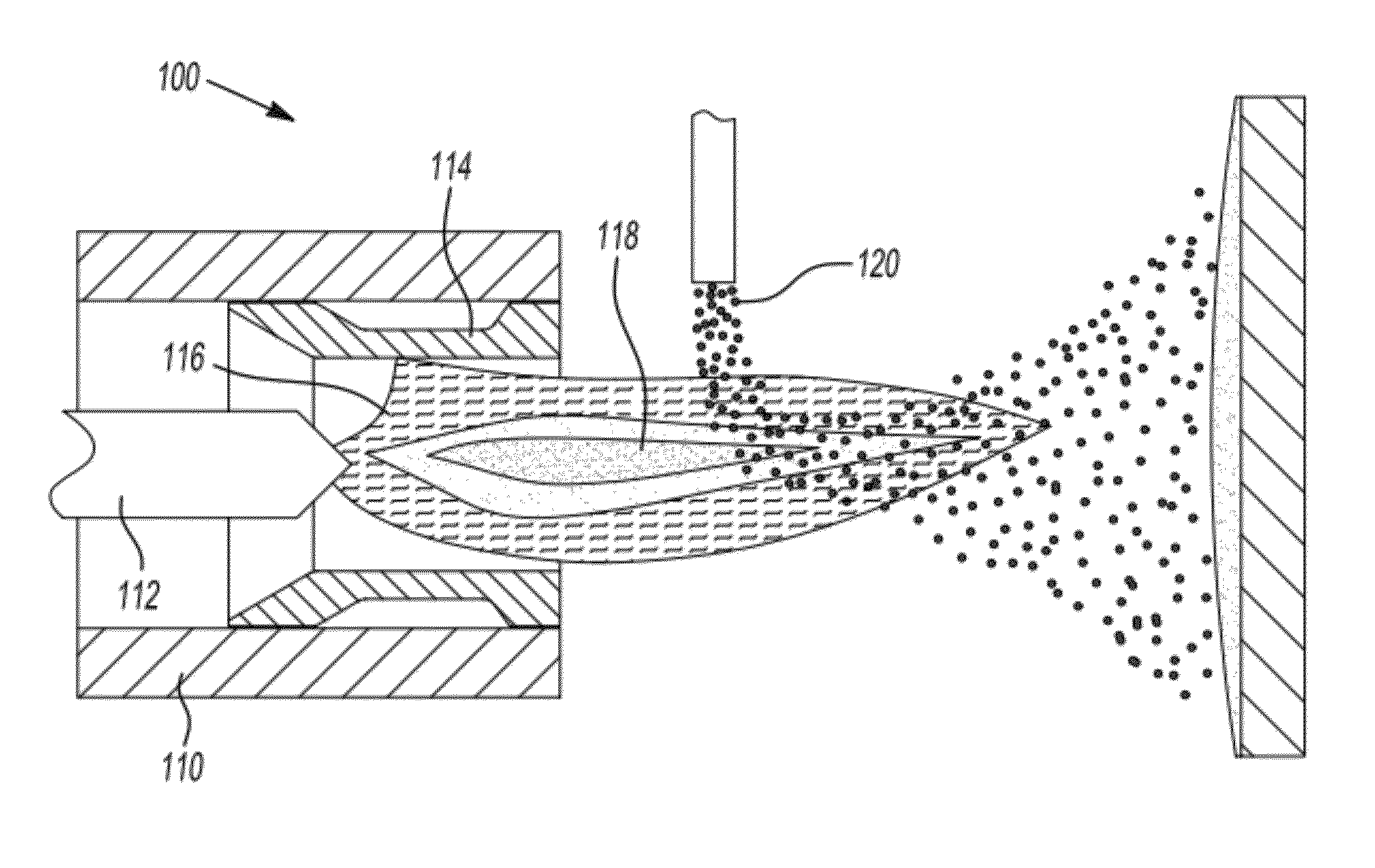
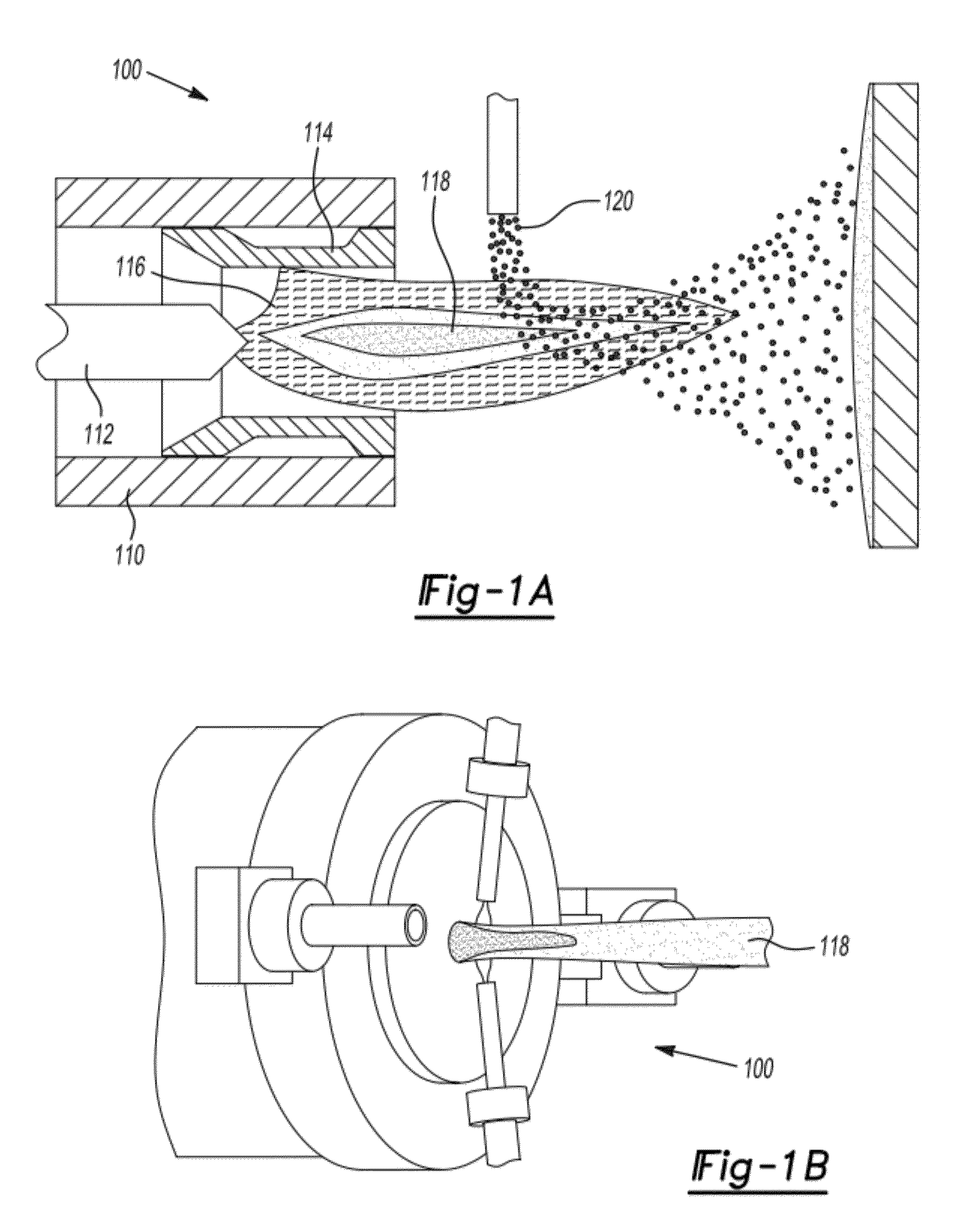
The patent text describes a modified direct current plasma processing apparatus and methods for improving coating results using direct current plasma processing. The invention addresses the non-uniformity of powder or droplets exposed to different temperature history or profiles as they travel with the plasma jet in direct current plasma processing. The invention also addresses the lower velocity of entrained particles due to the need to change direction within the jet from a radial direction to an axial direction and the associated inertias. The technical effects of the invention include improved coating quality and efficiency, as well as reduced non-uniformity of powder or droplets exposure.

Problems solved by technology

However, direct current plasma processing suffers from a number of disadvantages.
This temperature non-uniformity of powder or droplets affects the coating quality negatively.
This variation is especially disadvantageous in liquid-based techniques, which are typically used for nanomaterial synthesis.
This negatively affects the coating density and the deposition efficiency (i.e. amount of material injected compared to the amount that adheres to the target).
Similarly, in the case of liquid precursors, lack of appropriate heating leads to unconverted / unmelted material resulting in undesirable coating structures as illustrated in FIG. 22.
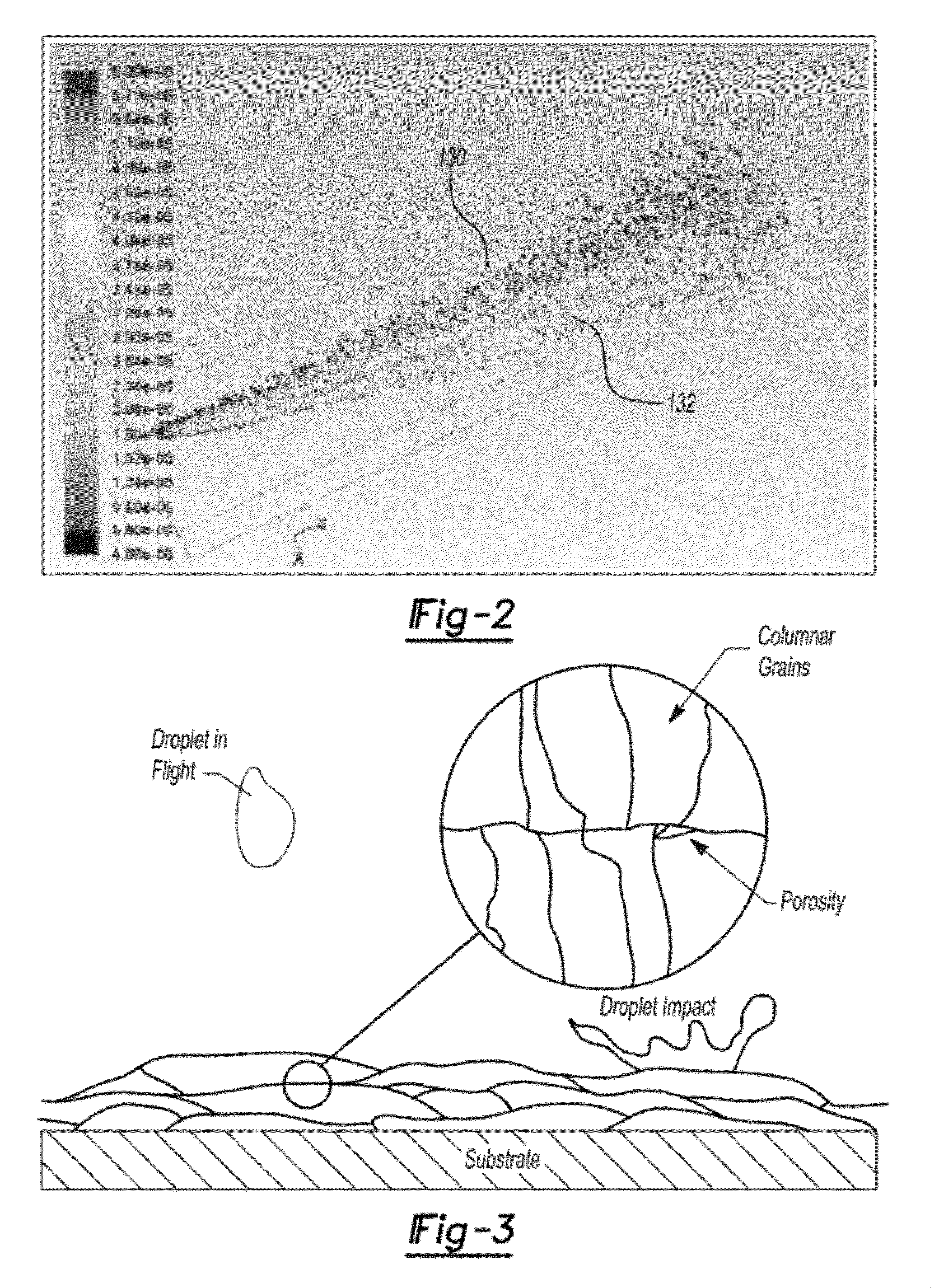
Furthermore, the coatings typically achieved with conventional direct current plasma processing suffer from additional disadvantages in that as individual molten or semi-molten particles impact a target, they often retain their boundaries in the solidified structure, as illustrated in FIG. 3.
These boundary characteristics and regions often lead to problems in the resultant coating and a suboptimal layer.
These compromised coatings are particularly undesired in biomedical, optical and electrical applications (i.e. solar and fuel cell electrolytes).

Method used


Image

  • In-situ plasma/laser hybrid scheme
  • In-situ plasma/laser hybrid scheme
  • In-situ plasma/laser hybrid scheme

Examples


Embodiment Construction

[0045]Example embodiments will now be described more fully with reference to the accompanying drawings.

[0046]Example embodiments are provided so that this disclosure will be thorough, and will fully convey the scope to those who are skilled in the art. Numerous specific details are set forth such as examples of specific components, devices, and methods, to provide a thorough understanding of embodiments of the present disclosure. It will be apparent to those skilled in the art that specific details need not be employed, that example embodiments may be embodied in many different forms and that neither should be construed to limit the scope of the disclosure.

[0047]The terminology used herein is for the purpose of describing particular example embodiments only and is not intended to be limiting. As used herein, the singular forms “a”, “an” and “the” may be intended to include the plural forms as well, unless the context clearly indicates otherwise. The terms “comprises,”“comprising,”“i...


PUM

PropertyMeasurementUnit
temperatureaaaaaaaaaa
melting pointaaaaaaaaaa
poweraaaaaaaaaa

Abstract

A method and apparatus for forming layers on a target. The apparatus and method employ a direct current plasma apparatus to form at least one layer using a plasma jet containing precursors. In some embodiments, the direct current plasma apparatus utilizes axial injection of the precursors through the cathode (in an upstream and / or downstream configuration) and / or downstream of the anode. In some embodiments, the direct current plasma apparatus can comprise a laser source for remelting the layer using a laser beam to achieve in-situ densification thereof.

Description

CROSS-REFERENCE TO RELATED APPLICATIONS[0001]This application claims the benefit of U.S. Provisional Application No. 61 / 174,576, filed on May 1, 2009 and U.S. Provisional Application No. 61 / 233,863, filed on Aug. 14, 2009. The entire disclosures of each of the above applications are incorporated herein by reference.GOVERNMENT INTEREST[0002]This invention was made with government support under Grant No. N00244-07-P-0553 awarded by the U.S. Navy. The government has certain rights in the inventionFIELD[0003]The present disclosure relates to direct current (DC) plasma processing and, more particularly, relates to a modified direct current plasma apparatus and methods for improved coating results using direct current plasma processing.BACKGROUND AND SUMMARY[0004]This section provides background information related to the present disclosure which is not necessarily prior art. This section provides a general summary of the disclosure, and is not a comprehensive disclosure of its full scope...

Claims


Application Information

Patent Timeline
Patent Type & Authority Patents(United States)
IPC IPC(8): B23K9/00
CPCH05H1/42G21K5/00H05G2/00H05H1/3478
Inventor MOHANTY, PRAVANSU S.MOROZ, NICHOLAS ANTON
Owner RGT UNIV OF MICHIGAN
Learn More