
Apparatuses and systems for density gauge calibration and reference emulation

a density gauge and reference emulation technology, applied in the direction of resistance/reactance/impedence, metal/alloy conductors, instruments, etc., can solve the problems of labor and time, and achieve the effect of reducing the size of typical reference standards, increasing the effective dielectric constant of standards, and small volum

Active Publication Date: 2012-10-30
TROXLER ELECTRONICS LAB INC
View PDF8 Cites 9 Cited by
  • Summary
  • Abstract
  • Description
  • Claims
  • Application Information

AI Technical Summary

Benefits of technology

The present invention relates to apparatuses and systems for calibrating and confirming the calibration of non-nuclear moisture-density quality control equipment, such as electromagnetic devices. The invention provides lightweight, portable, and easily integrated standards for calibration and operation. The invention can be used for low and high frequency instruments, and can be adjusted to emulate the dielectric constant of different materials. The invention can be used with various carrying cases and can be adjusted to account for changes in gauge geometry and other factors affecting calibration accuracy. The invention also provides artificial dielectrics for emulating the dielectric constant and frequency dependence of materials. Overall, the invention provides apparatuses and systems for accurately calibrating and confirming non-nuclear moisture-density quality control equipment.

Problems solved by technology

This ability to increase the reference plate area minimizes errors from spatial variability of the signal characteristics of the gauge, a disadvantage found in using existing reference standards (the conductive layer also eliminates the influence of the bottom earth layer on the measurement).
As described above, because of variations in manufacturing tolerances, sensing probes, such as electromagnetic devices, of the same design will not necessarily sense the same reading or same effective dielectric constant.
Both of these methods require the extraction and determination of actual density of core samples from the asphalt lane, which is both labor and time intensive.

Method used


Image

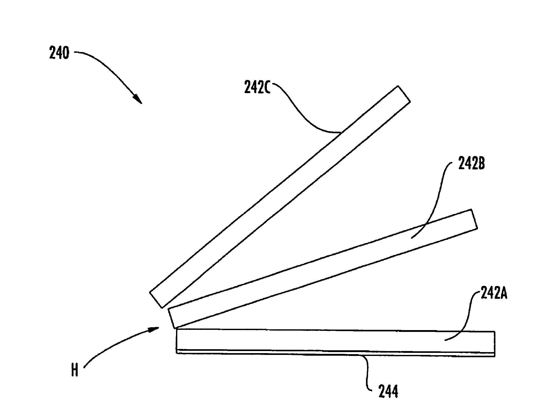
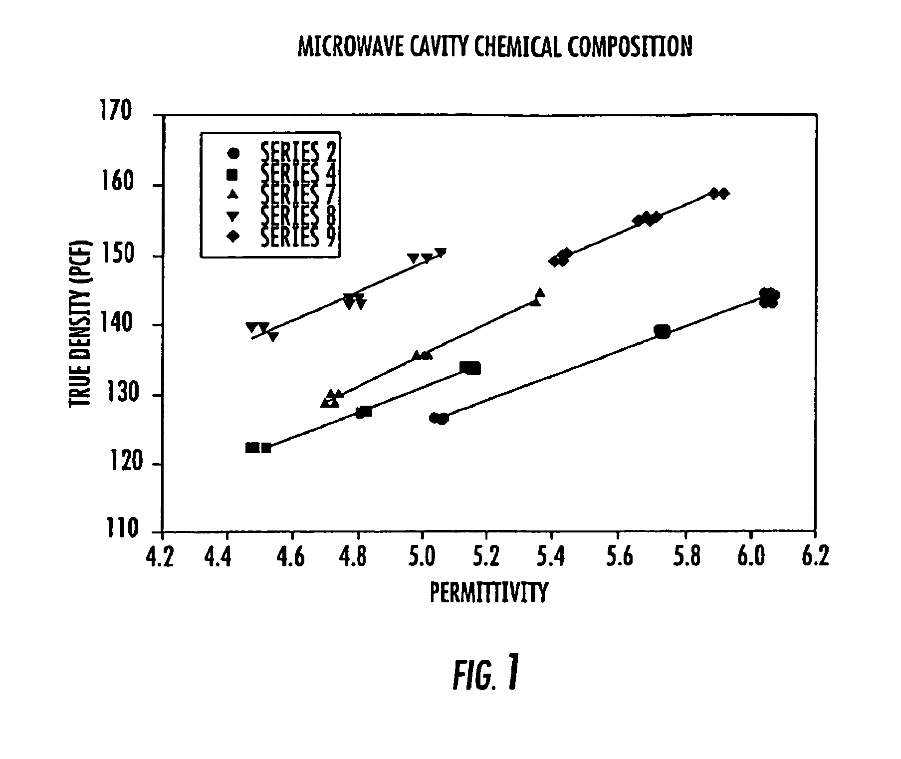
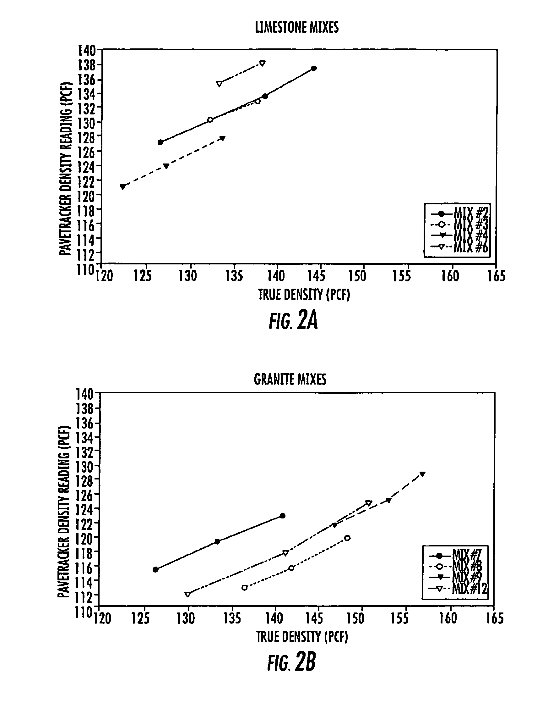
  • Apparatuses and systems for density gauge calibration and reference emulation
  • Apparatuses and systems for density gauge calibration and reference emulation
  • Apparatuses and systems for density gauge calibration and reference emulation

Examples


Embodiment Construction

Background of Artificial Dielectrics

[0062]Artificial dielectrics are basically large-scale models of a dipolar molecule, constructed by arranging conductors in a 3-D pattern. A lightweight binder of filler material such as polystyrene supports the conductors. The result is a manmade material that simulates an ordinary dielectric material with a dipole moment. The combined effect of all the individual conductors of the lattice is to produce a net dipole polarization P per unit volume. Artificial dielectrics are discussed extensively in the art, such as by W. E. Kock in “Metallic Delay Lines,”Bell System Technical Journal, vol. 27, pp. 58-82 (1948) and by Robert E. Collin in “Field Theory of Guided Waves,” Second Edition, IEEE Press (1991).

[0063]As shown in FIG. 5 (Collin), there are many shapes of conductors that one can use for artificial dielectrics, such as disks, needles, spheres, cylinders, etc. incorporated into a matrix. FIG. 5A illustrates a three-dimensional sphere medium; F...


PUM


Abstract

Apparatuses and systems for emulating electrical characteristics of a material having a known dielectric response are disclosed for standardizing and calibrating of electromagnetic devices. The emulator apparatus can include an electrically non-conductive layer having a dielectric constant less than the material dielectric constant and an electrically conductive layer adjacent the non-conductive layer. Artificial dielectrics for emulating the dielectric response of a material are also disclosed including a substrate matrix having a dielectric constant less than the material dielectric constant and an additive combined with the substrate, the additive having a dielectric constant higher than the material dielectric constant.

Description

RELATED APPLICATIONS[0001]This application is related to U.S. Provisional Patent Application Ser. No. 60 / 663,420, filed Mar. 18, 2005; and is a continuation of application Ser. No. 11 / 384,005 filed Mar. 17, 2006, now U.S. Pat. No. 7,705,614 the disclosures of which are incorporated herein by reference in its entirety.TECHNICAL FIELD[0002]The presently disclosed subject matter relates to standardization and calibration of electromagnetic devices. More particularly, the presently disclosed subject matter relates to apparatuses and systems for emulating electrical characteristics of a material having a known dielectric constant.BACKGROUND[0003]Pavement materials, such as soil, sand, aggregate, asphalt, and cement, typically require quality control testing during the construction process for physical attributes such as density, modulus, cement content, and moisture. The moisture and density relationship is an important property that is monitored during road construction and rehabilitati...

Claims


Application Information

Patent Timeline
Patent Type & Authority Patents(United States)
IPC IPC(8): G01R27/26
CPCG01R35/007H01B1/02G06F11/3652G01N27/00G01N27/221G06F11/261
Inventor TROXLER, ROBERT ERNEST
Owner TROXLER ELECTRONICS LAB INC
Learn More