Micro-bubble generating device

a technology of generating device and micro-bubble, which is applied in the direction of machines/engines, chemical/physical processes, and combustion gas purification/modification, etc. it can solve the problems of high manufacturing cost, comparatively complicated device construction, and inability to really qualify the bubble generated and mixed into the liquid as micro-bubbles, so as to achieve more economical dispersion and simple and compact construction

Active Publication Date: 2012-11-06
NAKASHIMA IND
View PDF28 Cites 10 Cited by
  • Summary
  • Abstract
  • Description
  • Claims
  • Application Information

AI Technical Summary

Benefits of technology

[0010]The present invention was made in view of the background art described above. It is therefore an object of this invention to provide a micro-bubble generating device which is simple in construction and more economical to manufacture and which permits increased reliability of mixing or dispersing micro-bubbles into a liquid. It is another object of the invention to provide a micro-bubble generating device which permits increased stability of generation of a sufficient amount of micro-bubbles even after a long period of use in water.
[0026]Accordingly, the micro-bubble generating device of the present invention described above permits stable mixing of the micro-bubbles into various kinds of liquid, without large-scale equipment, that is, with a simple construction that can reduce cost of manufacture. As a result, by thus mixing or dispersing the micro-bubbles in fuel oil and other oils, for example, combustion efficiency of the oils can be effectively improved. Further, by mixing micro-bubbles of carbonic acid gas into water, water containing the micro-bubbles of carbonic acid gas can be obtained. The water or other liquids containing such micro-bubbles can be not only utilized for liquid purification and as washing or drinking water, but also effectively utilized for wastewater or drainage treatment and other waste-liquid treatments, and for activation of microorganisms.
[0028]In the micro-bubble generating device of the invention, the micro-bubble generating sleeve is rotated in the water by the rotary driving means while the gas is introduced from the external source into the space within the sleeve of the cylindrical substrate of the micro-bubble generating sleeve, through the gas introducing mechanism, whereby the micro-bubbles can be ejected from the outer surface portion of the unwoven fabric layer and is dispersed into the water. Thus, it is possible to generate the micro-bubbles from the outer surface portion of the unwoven fabric layer. In particular, the micro-bubble generating sleeve is rotated within the water, making it difficult for microorganisms, suspended matters and other foreign matters in the water, to adhere to the outer surface portion (outer circumferential surface) of the unwoven fabric layer or enter into the pores in the unwoven fabric layer. Even if such foreign matters adhere to the outer surface portion of the unwoven fabric layer or enter into the pores, the foreign matters can be effectively removed from the outer surface portion or pores of the unwoven fabric layer, by a centrifugal force produced by the rotation of the micro-bubble generating device. Therefore, the pores in the outer surface portion of the unwoven fabric layer can continually maintain sufficient areas of opening and volumes with a high degree of stability, for a long period of use of the micro-bubble generating device in the water.
[0029]Accordingly, the micro-bubble generating device of the invention described above permits stable generation of the further small-sized micro-bubbles in a sufficient amount, and ejection and dispersion of the micro-bubbles into the water, during a long period of use in the water. As a result, the micro-bubble generating device capable of dispersing the micro-bubbles into the water can exhibit a desired effect of activation of domestic animals or plants, or purification of wastewater or drainage, for example, with an extremely high degree of stability for a longer period of time.
[0031]Accordingly, the micro-bubble generating device of the invention described above can be more effectively made simpler and more compact in construction, and permits more economical dispersion of the small-sized micro-bubbles into the water. Here, it is to be understood that the micro-bubbles include bubbles having a nano-meter size.

Problems solved by technology

In such a conventional device, the screw portion of the stationary type mixer has the helical blades disposed within the cylindrical body, and the cutter portion has the plurality of protrusions formed on the inner circumferential surface of the cylindrical body, so that the device is comparatively complicated in construction, and has an accordingly high cost of manufacture.
Further, the bubbles generated and mixed into the liquid cannot be really qualified as the micro-bubbles.

Method used


Image

  • Micro-bubble generating device
  • Micro-bubble generating device
  • Micro-bubble generating device

Examples


Embodiment Construction

[0047]To further clarify the present invention, embodiments of the present invention will be described in detail by reference to the drawings.

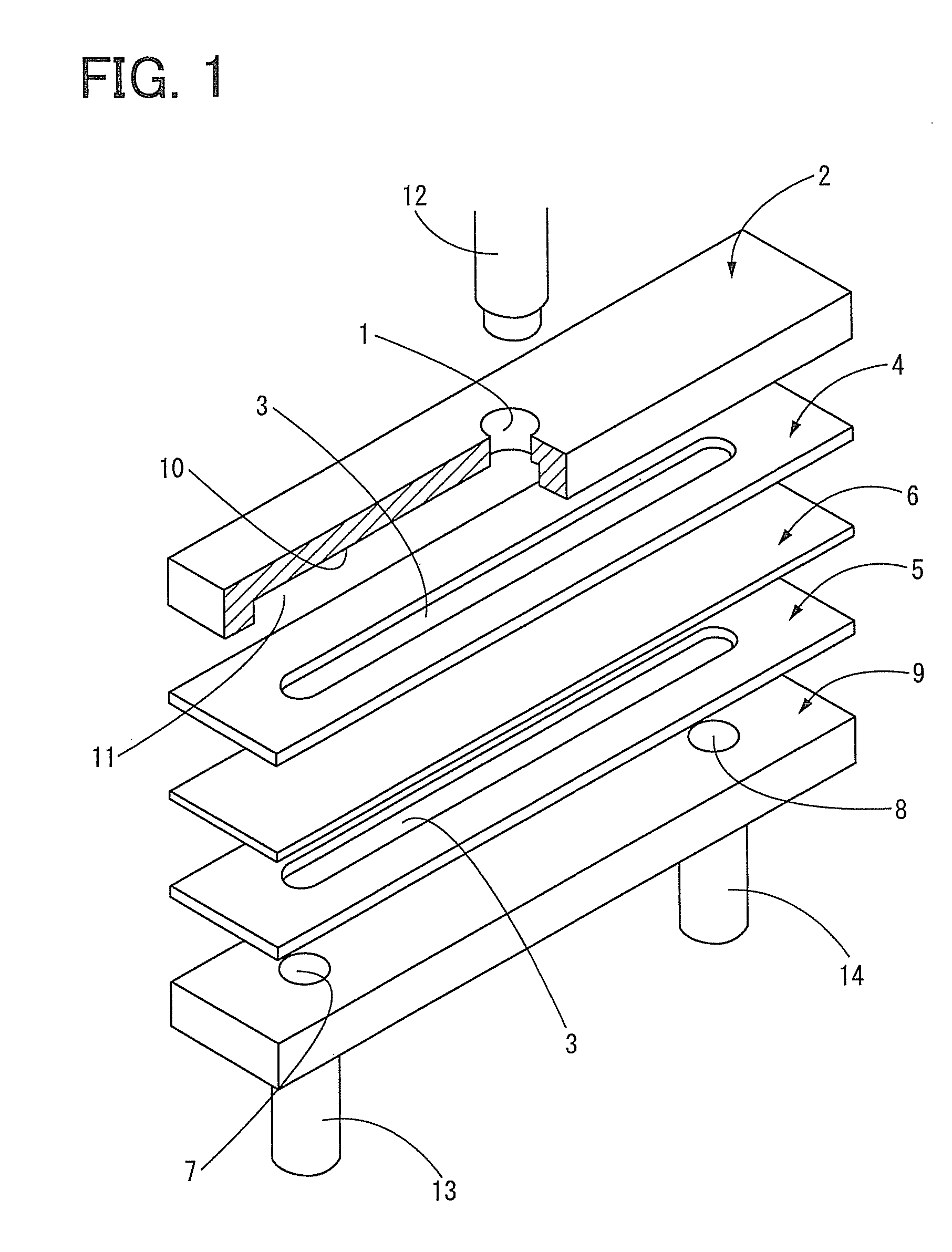
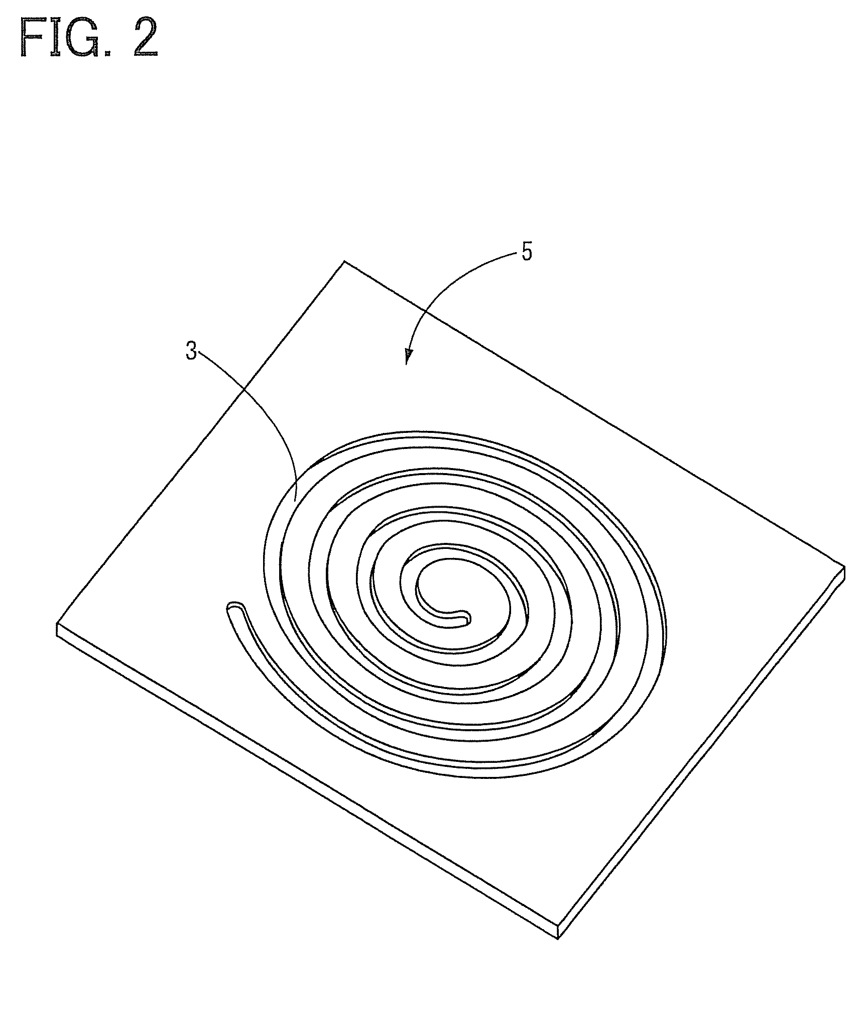
[0048]Referring first to the exploded perspective view of FIG. 1, there is shown one embodiment of a micro-bubble generating device having a construction of the present invention. As is apparent from FIG. 1, the micro-bubble generating device of the present embodiment has at least: a first member in the form of a gas supply member 2 having an elongate planar shape with a gas inlet 1 formed in its longitudinally central portion; a first packing 4 and a second packing 5 each of which has an elongate planar shape with a small thickness having a fluid passage 3 extending in its longitudinal direction; a gas-permeable film 6; and a second member in the form of a liquid flow member 9 which has an elongate planar shape with a liquid inlet 7 and a liquid outlet 8 respectively formed in its longitudinally opposite end portions.

[0049]On the opposite sid...


PUM

PropertyMeasurementUnit
sizeaaaaaaaaaa
thicknessaaaaaaaaaa
thicknessaaaaaaaaaa

Abstract

A micro-bubble generating device is provided which is capable of mixing or dispersing micro-bubbles into a liquid with high stability and has a simple structure that permits reduction of a cost of manufacture. A first member and a first packing are superposed on each other on one side of a gas-permeable film, while a second member and a second packing are superposed on each other on the other side of the gas-permeable film. A pressurized gas delivered via a gas inlet of the first member flows through a fluid passage of the first packing, permeates through the gas-permeable film, and is ejected as micro-bubbles into a liquid flowing through a fluid passage in the form of a narrow shallow strip-like groove provided in the second packing.

Description

[0001]This application is a continuation of the International Application No. PCT / JP2010 / 052195 filed on Feb. 15, 2010, which claims the benefit under 35 U.S.C. §119(a)-(d) of Japanese Patent Application No. 2009-033479, filed on Feb. 17, 2009, Japanese Patent Application No. 2009-229616, filed on Oct. 1, 2009, and Japanese Utility Model Registration Application No. 2010-000197, filed on Jan. 14, 2010, the entireties of which are incorporated herein by reference.FIELD OF THE INVENTION[0002]The present invention relates to a micro-bubble generating device, and more particularly to improvements of a micro-bubble generating device constructed to generate micro-bubbles and mix the micro-bubbles into (with) a liquid or disperse the micro-bubbles into the liquid.BACKGROUND OF THE INVENTION[0003]In recent years, it has been recognized that bubbles of a size not larger than 1 mm called “micro-bubbles” have various excellent properties, and such micro-bubbles have been drawing a lot of atten...

Claims


Application Information

Patent Timeline
Patent Type & Authority Patents(United States)
IPC IPC(8): B01F3/04B01F33/40
CPCA01K63/042B01F3/04269C02F3/201B01F2003/04276C02F2103/20B01F2003/04404B01F2003/04858B01F2003/04319Y02W10/10B01F23/23125B01F23/23124B01F23/231244B01F23/231265B01F23/2373A01K63/04B01F23/20B01F25/40B01F27/60B01F23/2375
Inventor NAKASHIMA, YOJIYAMADA, KOJI
Owner NAKASHIMA IND
Why Eureka
Try Eureka