
Section processing method and its apparatus

a processing method and section technology, applied in the direction of instruments, semiconductor/solid-state device testing/measurement, basic electric elements, etc., can solve the problems of increasing the processing time period, invariably posing problems similar to patent reference 1, and achieve the effect of processing efficiency of section processing

Active Publication Date: 2012-11-06
HITACHI HIGH TECH SCI CORP
View PDF4 Cites 3 Cited by
  • Summary
  • Abstract
  • Description
  • Claims
  • Application Information

AI Technical Summary

Benefits of technology

This approach reduces processing time by allowing simultaneous observation and processing, enabling efficient detection of the processing position directly from the observation image, thus improving processing efficiency.

Problems solved by technology

However, according to the above-described section processing method and its apparatus of the background art, the following problem is posed.
Therefore, after subjecting one processing face to section processing, observation of the processing face and detection of the mark need to be carried out separately from each other, and therefore, a problem that a processing time period is increased is posed.
Therefore, with regard to whether the processing face is progressed up to a target position, the mark on the side of the processing face needs to be observed, and therefore, a problem similar to that of Patent Reference 1 is invariably posed.

Method used


Image

  • Section processing method and its apparatus
  • Section processing method and its apparatus
  • Section processing method and its apparatus

Examples


Embodiment Construction

[0045]An embodiment of the invention will be explained in reference to the attached drawings as follows.

[0046]First, a section processing apparatus according to an embodiment of the invention will be explained.

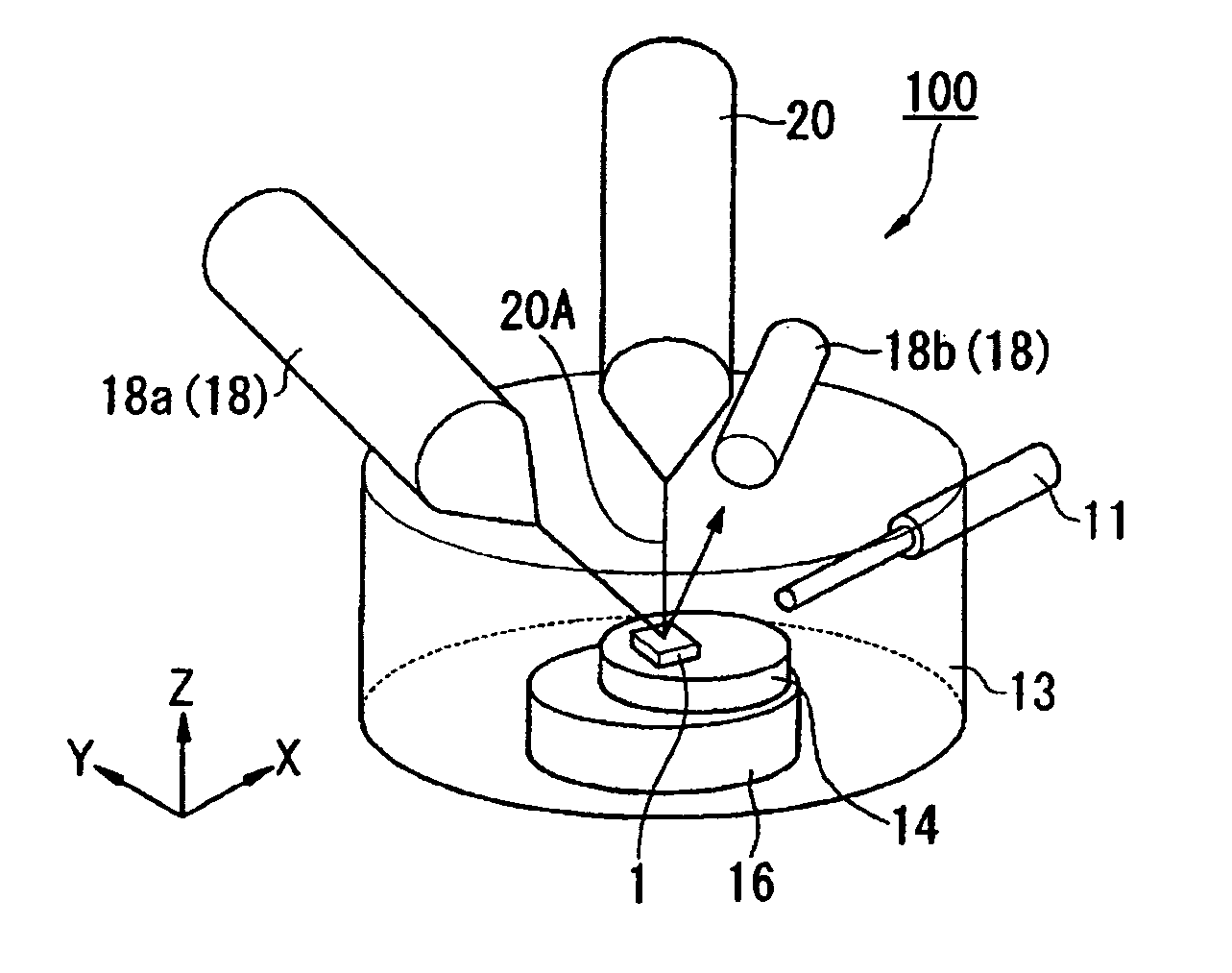
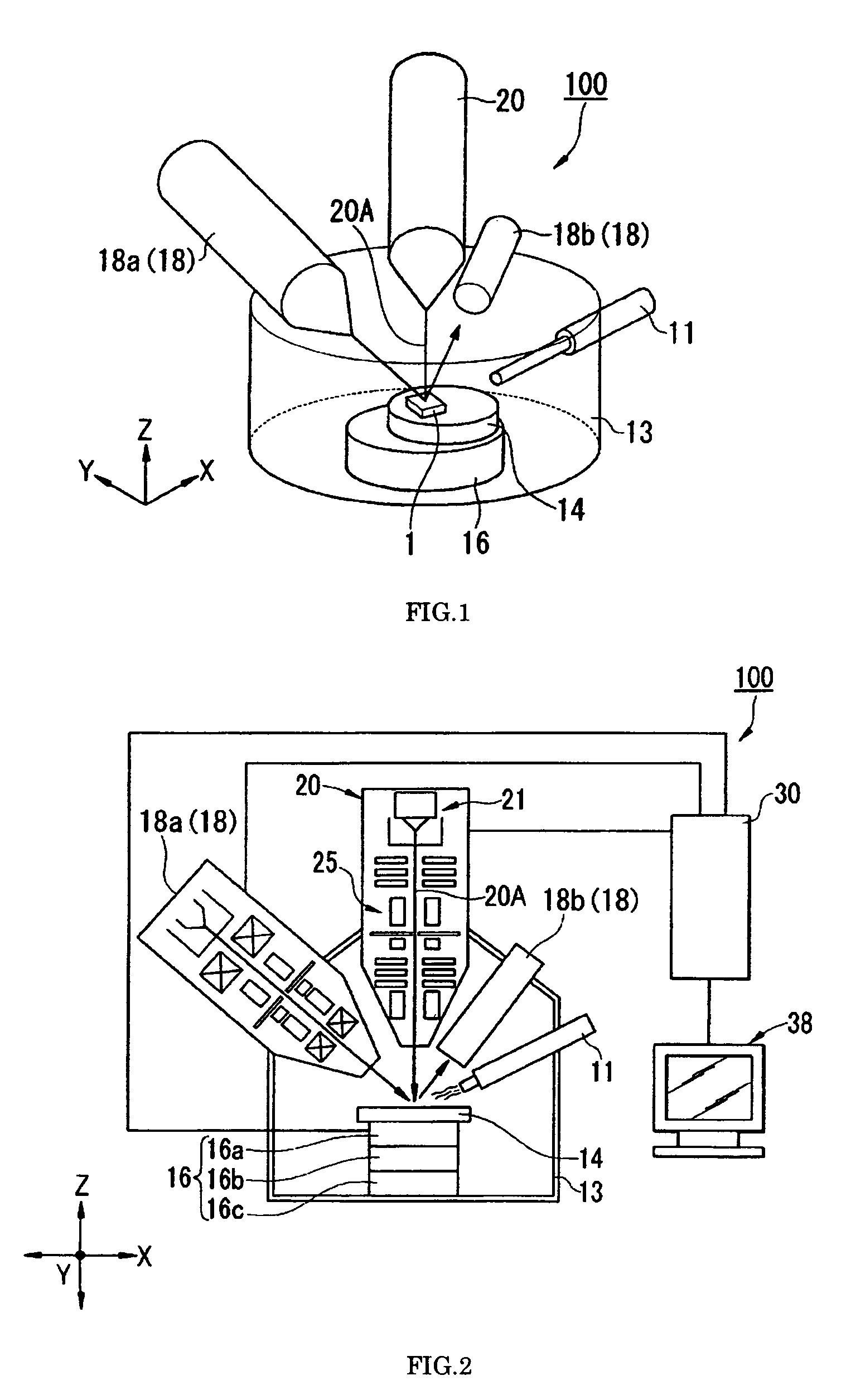
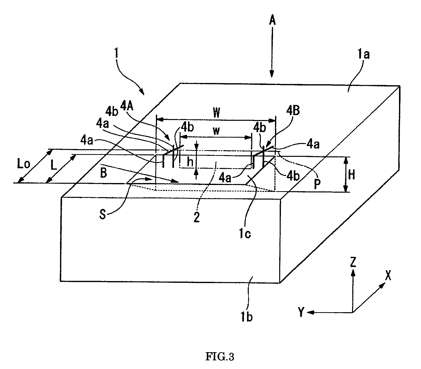
[0047]FIG. 1 is a schematic perspective view showing an outline constitution of a section processing apparatus according to an embodiment of the invention. FIG. 2 is a schematic sectional view showing the outline constitution of the section processing apparatus according to the embodiment of the invention. FIG. 3 is a schematic perspective view showing a behavior of a sample in being processed by the section processing apparatus according to the embodiment of the invention. FIG. 4 is functional block diagram of a control unit of the section processing apparatus according to the embodiment of the invention. Further, an XYZ coordinates system described in the drawings are provided commonly to the respective drawings for convenience of reference of directions, a Z axis positive d...


PUM


Abstract

A section processing apparatus has a mark forming control portion that transmits control information for forming marks on a surface of a sample. Each of the marks has at least two portions intersecting at a converging portion located at a previously determined position of an observation target section of the sample or in the vicinity of the previously determined position. A first focused ion beam apparatus emits a first focused beam for forming each of the marks on the surface of the sample based on the control information transmitted by the mark forming control portion and for processing a section of the sample. The section of the sample is processed by scanning the first focused beam in parallel with the at least two portions of the marks in the direction of the converging portion, while the section of the sample and positions of the marks are observed by a second focused ion beam apparatus, and to finish processing of the section of the sample when the first focused beam reaches the converging portion or a vicinity thereof.

Description

BACKGROUND OF THE INVENTION[0001]1. Field of the Invention[0002]The present invention relates a section processing method and its apparatus. The invention relates to a section processing method and its apparatus of forming a section for observation by moving a processing position by successively carrying out removal processing for a sample, when for example, a defect of an inner portion of a semiconductor chip is observed.[0003]2. Background Information[0004]In a background art, when, for example, a failure at an inner portion of a semiconductor chip is observed, a section for observation is formed by rupturing a sample by a focused ion beam and observing the section by an electron microscope. With regard to the section for observation, for example, a position of a defect of a sample is specified by a defect inspection apparatus, and section processing is carried out based on the position information. That is, removal processing is successively repeated by irradiating a focused ion ...

Claims


Application Information

Patent Timeline
Patent Type & Authority Patents(United States)
IPC IPC(8): G06K9/00
CPCH01J37/28H01J37/3056H01J37/31H01L21/67282H01L23/544H01J2237/28H01J2237/31745H01J2237/31749H01L2223/5442H01L2223/54426H01L2223/54453H01L2924/0002H01L2924/00H01L21/00H01L22/00
Inventor FUJII, TOSHIAKITASHIRO, JUNICHIHASSEL-SHEARER, MIKE
Owner HITACHI HIGH TECH SCI CORP
Learn More