
Method for manufacturing head gimbal assembly, and method for manufacturing hard disk drive

a manufacturing method and gimbal technology, applied in the direction of maintaining head carrier alignment, recording information storage, instruments, etc., can solve the problems of high manufacturing cost, easy mass production, and improvement, and achieve the effect of suppressing the characteristic reduction, reducing the characteristic, and recovering the characteristic easily

Active Publication Date: 2012-11-13
TDK CORPARATION +1
View PDF9 Cites 1 Cited by
  • Summary
  • Abstract
  • Description
  • Claims
  • Application Information

AI Technical Summary

Benefits of technology

[0011]In accordance with the method for manufacturing the head gimbal assembly according to the aspect of the invention, it is possible to obtain a head gimbal assembly comprised of a thin film piezoelectric actuator including a pair of piezoelectric laminates, each having a monolayer piezoelectric layer, that is, a monolayer type thin film piezoelectric actuator. Furthermore, in accordance with the method for manufacturing a head gimbal assembly according to the aspect of the invention, after fixing a thin film piezoelectric actuator to a suspension, each of the first piezoelectric layer and the second piezoelectric layer is subjected to repolarization treatment. Therefore, upon fixing the thin film piezoelectric actuator to a suspension, even if the thin film piezoelectric actuator is subjected to stress, and an electric field is generated in the first piezoelectric layer and the second piezoelectric layer by a positive piezoelectric effect, and the direction of the piezoelectric polarization of the first piezoelectric layer and the second piezoelectric layer is fluctuated or is reversed by this electric field, it is possible to restore the directions of the piezoelectric polarization of the first piezoelectric layer and the second piezoelectric layer to the original state, or to make them approach to the original state. As a result, it is possible to suppress the characteristic reduction of the thin film piezoelectric actuator resulting from the direction of piezoelectric polarization fluctuating or being reversed.
[0030]In accordance with the present invention, there is provided a method for manufacturing a head gimbal assembly comprising a monolayer type thin film piezoelectric actuator, and a method for manufacturing a hard disk drive comprising such a head gimbal assembly, capable of suppressing the characteristic reduction resulting from the direction of piezoelectric polarization fluctuating or being reversed, and a head gimbal assembly comprising a monolayer type thin film piezoelectric actuator and a hard disk drive comprising such a head gimbal assembly, capable of suppressing the characteristic reduction resulting from the direction of piezoelectric polarization fluctuating or being reversed.

Problems solved by technology

Therefore, they have problems in that the structure is complicated, mass production cannot be easily done, and the manufacturing cost is high.
In contrast, if a thin film piezoelectric actuator includes a pair of piezoelectric laminates, each having a monolayer piezoelectric layer, such problems improve.
In contrast, in monolayer type thin film piezoelectric actuators, the reduction in the characteristic of the thin film actuator resulting from problems such as the direction of the piezoelectric polarization fluctuating or reversing, as described above, poses a big problem.

Method used


Image

  • Method for manufacturing head gimbal assembly, and method for manufacturing hard disk drive
  • Method for manufacturing head gimbal assembly, and method for manufacturing hard disk drive
  • Method for manufacturing head gimbal assembly, and method for manufacturing hard disk drive

Examples


first embodiment

[0049

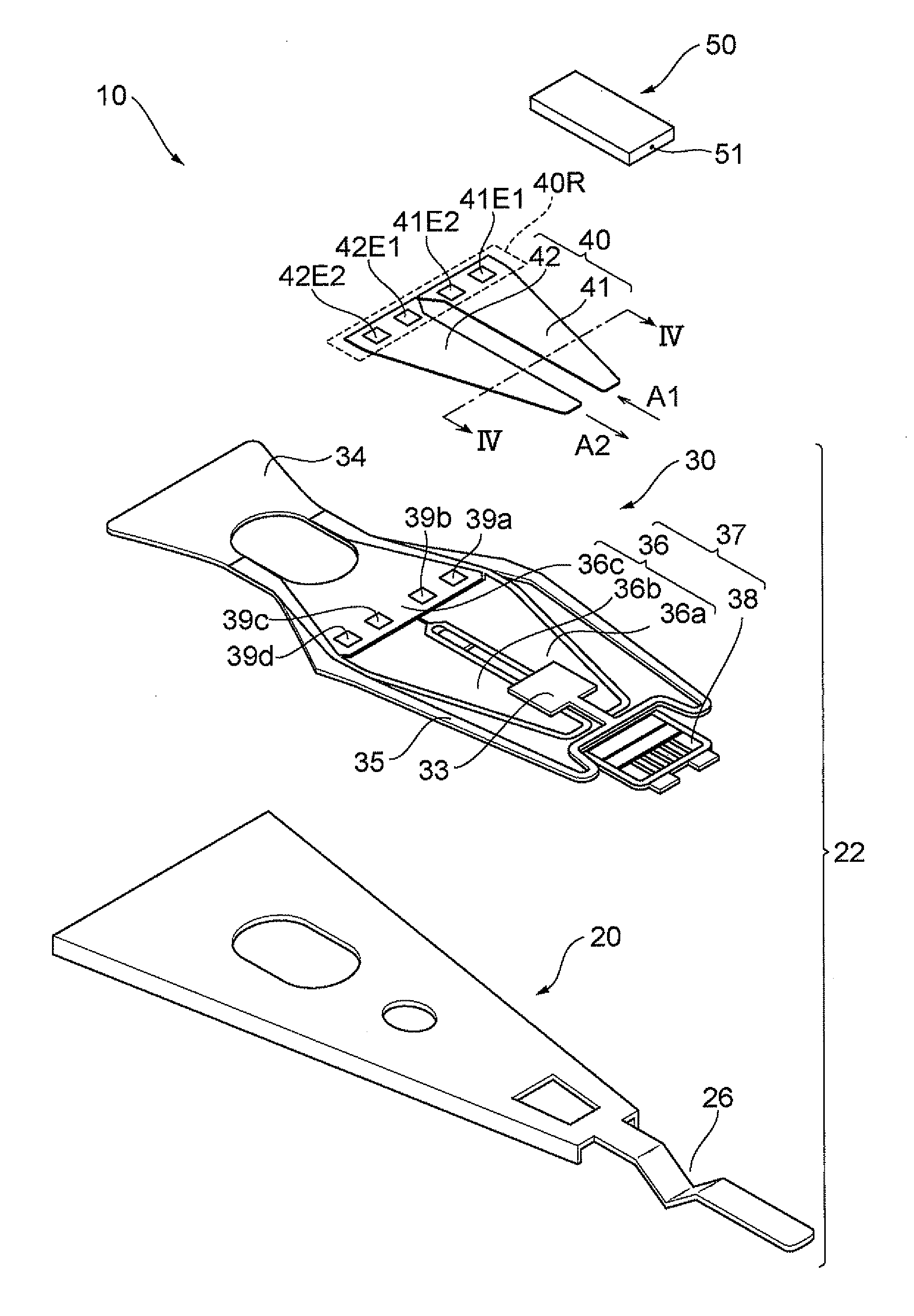
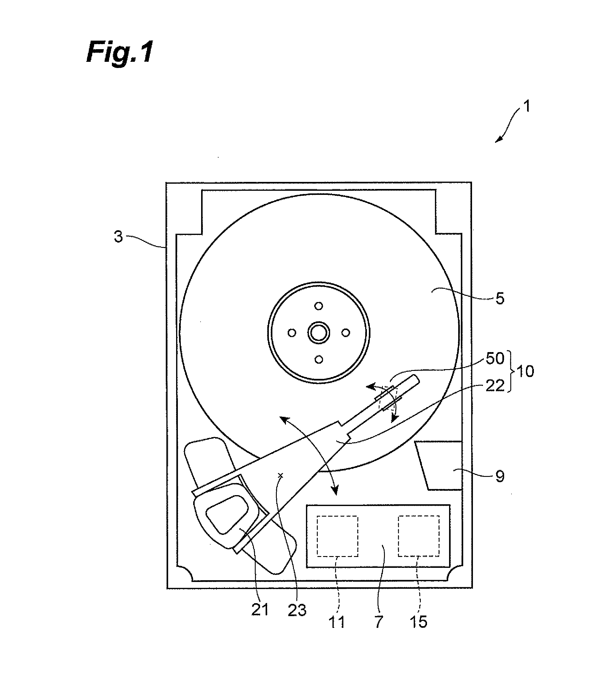
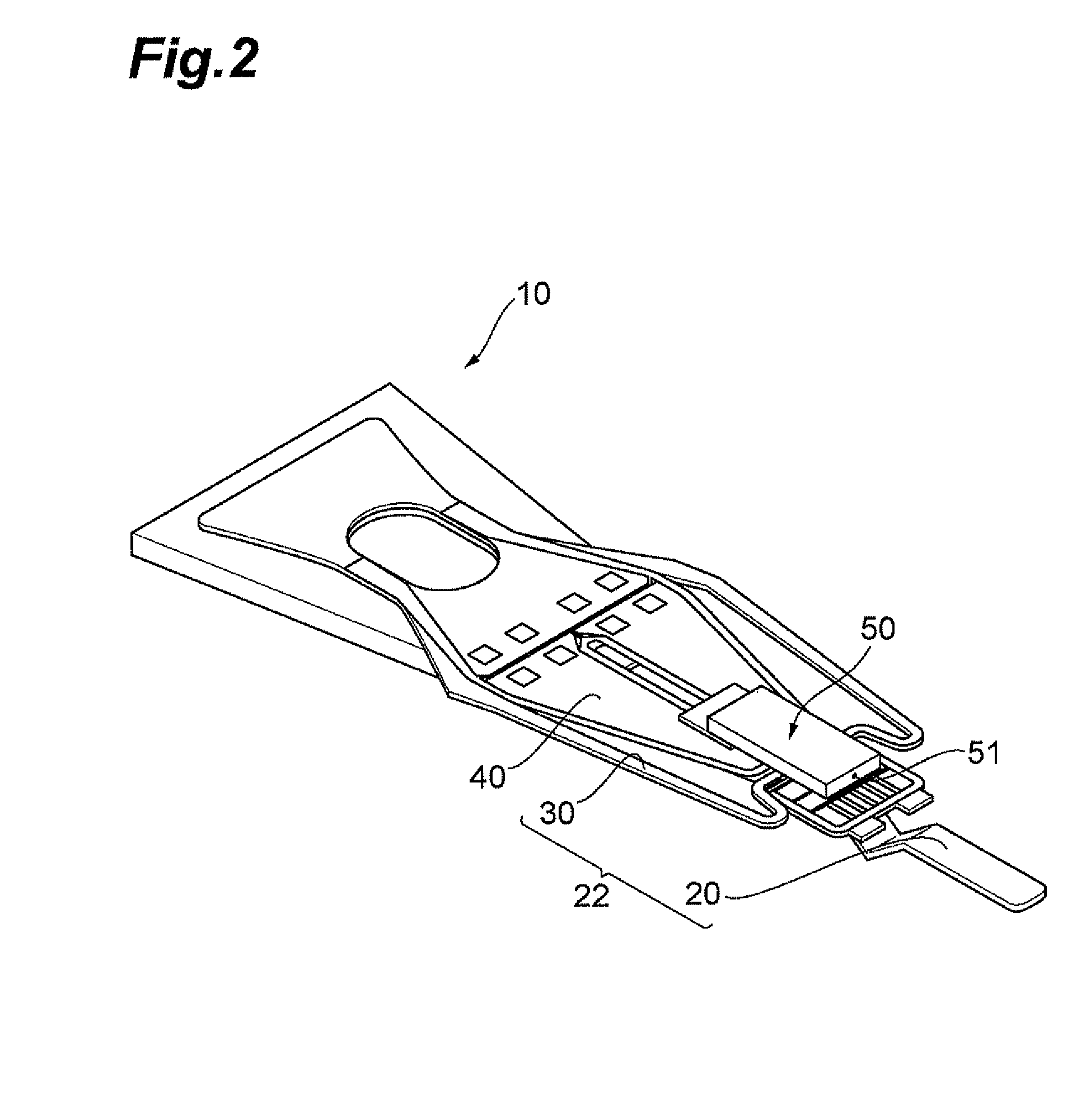
[0050]In the following, an HGA and a hard disk drive in accordance with the first embodiment will be described. FIG. 1 is a schematic view illustrating a hard disk drive comprising an HGA in accordance with the present embodiment. The hard disk unit 1 operates an HGA 10, and records and reproduces magnetic information onto and from a recording surface of a hard disk 5 which functions as a magnetic recording medium that rotates at high speed using thin film magnetic heads of ahead slider 50.

[0051]The hard disk unit 1 includes in its housing 3, the hard disk 5, the HGA 10 to which and from which magnetic information is recorded and reproduced, a control unit 7 which, for example, performs control of recording and reproduction of magnetic information onto and from the hard disk 5 by the HGA 10, and a ramp mechanism 9 for evacuating the thin film magnetic head from the hard disk 5.

[0052]The hard disk 5 is rotated by a motor. The HGA 10 is capable of rotating around a pivot 23 by me...

second embodiment

[0110

[0111]Now, a method for manufacturing an HGA in accordance with the second embodiment and a method for manufacturing a hard disk drive will be described.

[0112]FIG. 12 is a flow chart showing the method for manufacturing an HGA and the method for manufacturing a hard disk drive in accordance with the present embodiment. As shown in the flow chart 100a in FIG. 12, the method for manufacturing the hard disk drive in accordance with the present embodiment is different from the first embodiment in that, in a HGA manufacturing step S100Ha corresponding to the HGA manufacturing step S100H of the first embodiment, the electrical connecting step S107 is performed after the first repolarization treatment step S109 and the second repolarization treatment step S111, the method further comprises an inter-electrode connecting step S112 for electrically-connecting the first electrode pad 39a to the fourth electrode pad 39d and electrically-connecting the second electrode pad 39b to the third ...


PUM

PropertyMeasurementUnit
electrical potentialaaaaaaaaaa
thicknessaaaaaaaaaa
areaaaaaaaaaaa

Abstract

A method for manufacturing an head gimbal assembly (HGA) according to the present invention is comprised of: a step for preparing a thin film piezoelectric actuator including a first piezoelectric laminate having a first piezoelectric layer, and a second piezoelectric laminate having a second piezoelectric layer; a step for preparing a suspension; a fixing step for fixing the thin film piezoelectric actuator to the suspension; a first repolarization treatment step for performing repolarization treatment to the first piezoelectric layer after the fixing step; and a second repolarization treatment step for performing repolarization treatment to the second piezoelectric layer after the fixing step.

Description

BACKGROUND OF THE INVENTION[0001]1. Field of the Invention[0002]The present invention relates to a method for manufacturing a head gimbal assembly, a method for manufacturing a hard disk drive, a head gimbal assembly, and a hard disk drive.[0003]2. Related Background Art[0004]In order to increase the density and the capacity of a hard disk drive, the need for thin film piezoelectric actuators for use in high precision positioning mechanisms for tracking is becoming increasingly high in recent years. By arranging a thin film piezoelectric actuator in a head gimbal assembly comprised of a head slider and a suspension to which the head slider is mounted, the head slider can be minutely displaced using a thin film piezoelectric actuator. Thus, it is possible to obtain a head gimbal assembly capable of controlling the position of a head slider with high precision. Japanese Patent Application Laid-Open No. 2004-281651 describes an example of such a thin film piezoelectric actuator.[0005]T...

Claims


Application Information

Patent Timeline
Patent Type & Authority Patents(United States)
IPC IPC(8): G11B5/127H04R31/00G11B21/10G11B21/21
CPCG11B5/4826G11B5/4833G11B5/4873H01L41/0986H01L41/25H01L41/29H01L41/257Y10T29/49032Y10T29/49027Y10T29/4903Y10T29/42Y10T29/49025H10N30/206H10N30/03H10N30/06H10N30/045
Inventor HATA, KENJIRO
Owner TDK CORPARATION
Learn More