Control circuit and method for negative pressure wound treatment apparatus

a control circuit and negative pressure technology, applied in the direction of suction devices, intravenous devices, other medical devices, etc., can solve the problems of large or infected wounds, inability to spontaneously close, wounds that cannot successfully fight bacterial infections, etc., to prevent the stalling of the pump motor

Active Publication Date: 2012-11-13
SMITH & NEPHEW INC
View PDF141 Cites 139 Cited by
  • Summary
  • Abstract
  • Description
  • Claims
  • Application Information

AI Technical Summary

Benefits of technology

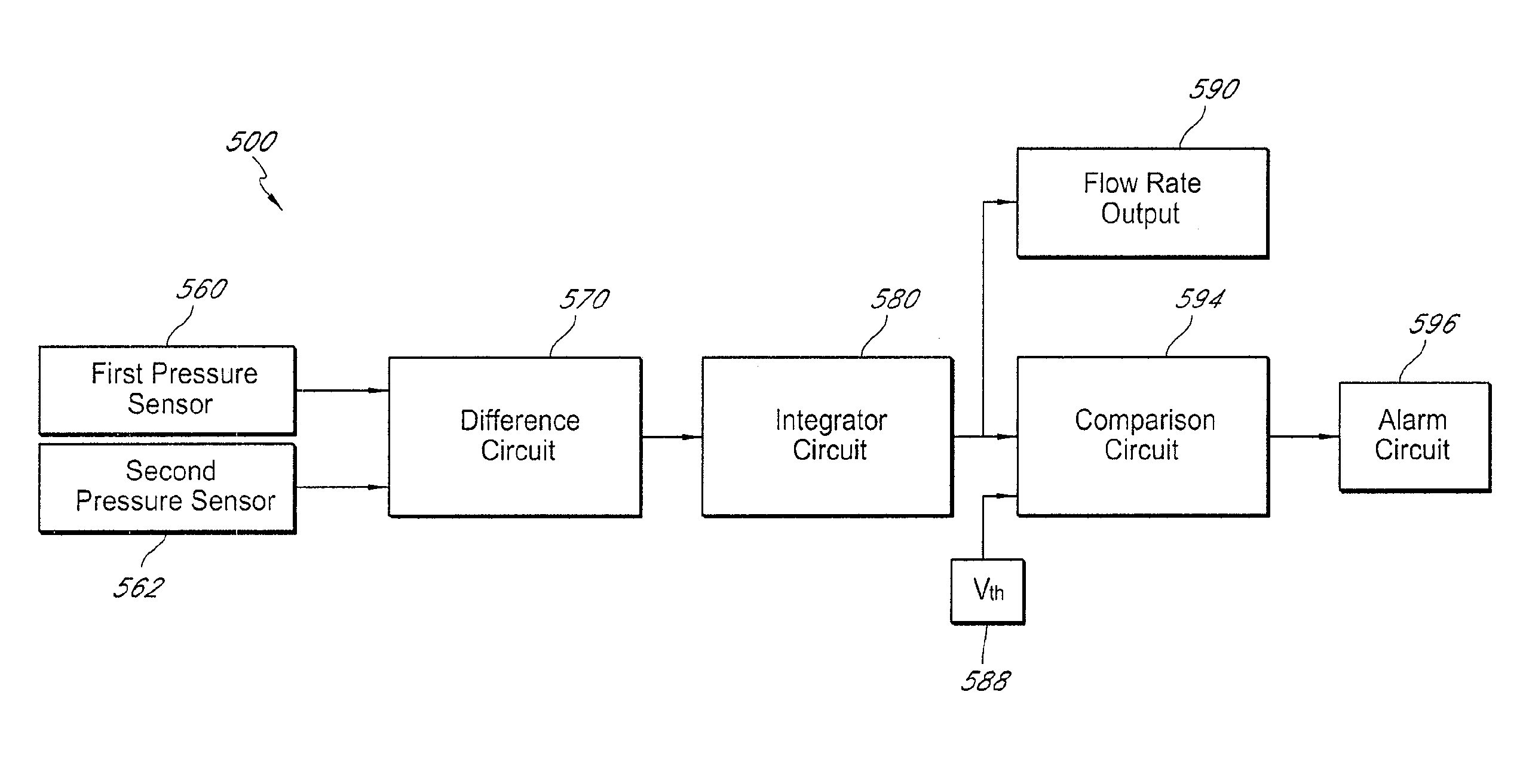
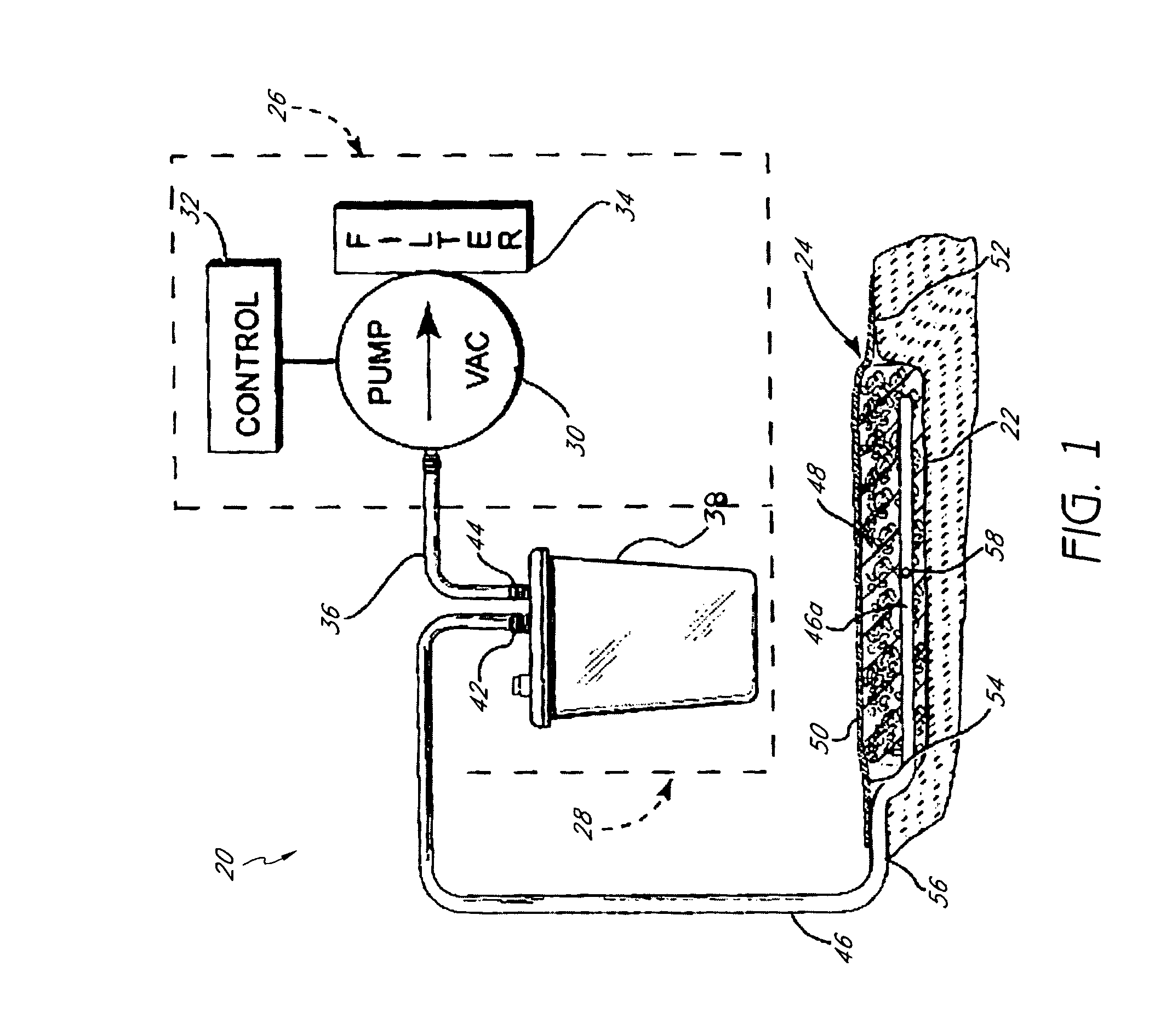
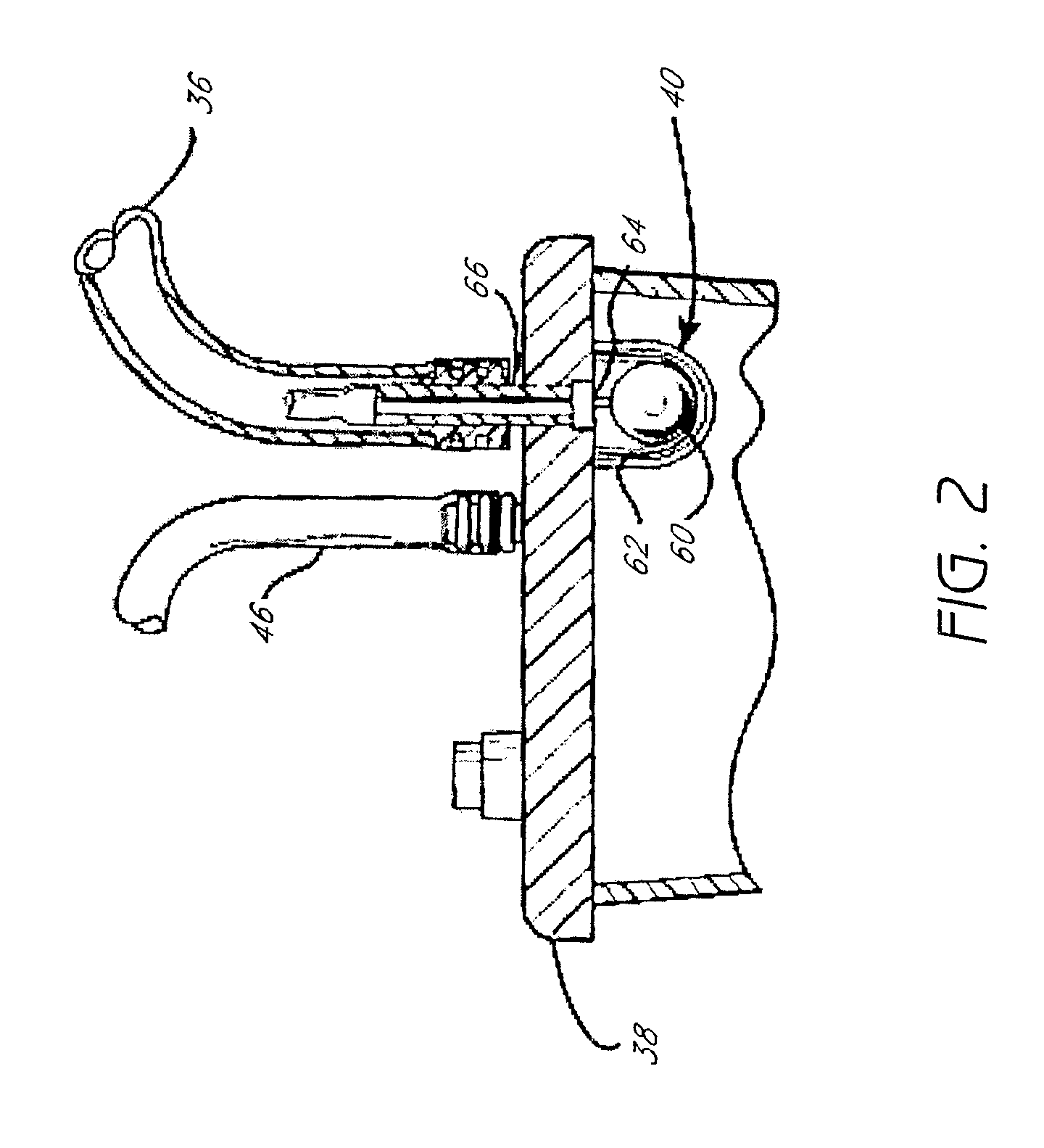
[0012]In some embodiments, such wounds are treated using a negative pressure wound therapy apparatus preferably comprising a wound dressing, a fluid collection container, a vacuum pump comprising a pump motor, and tubing. In addition, in some embodiments, the apparatus can include a pressure sensor that measures a pressure in the tubing. In some embodiments, one or more tubes of the tubing can channel a fluid between the wound dressing, the fluid collection canister, and the pump. In addition, in some embodiments, first and second control circuits can be provided for controlling the pump motor without using a processor. In some embodiments, the first control circuit can generate a difference signal between a desired pressure input and a pressure sensor input, and can further generate a motor control signal responsive to the difference signal. Moreover, in some embodiments, a second control circuit can provide an override signal based at least in part on the difference signal and at least one reference signal. In some embodiments, the override signal preferably beneficially overrides the motor control signal to prevent the pump motor from stalling.
[0013]In some embodiments, such wounds are treated using a negative pressure wound therapy apparatus preferably comprising a wound dressing, a fluid collection container, a vacuum pump comprising a pump motor, one or more tubes, a pressure sensor configured to measure a pressure in one or more of said one or more tubes and to generate a pressure sensor signal, a first control circuit to control the pump motor without using a processor, and a second control circuit. In some embodiments, the tubes are preferably configured to at least channel a flow of fluid between the wound dressing, the fluid collection canister, and the pump. In some embodiments, the first control circuit is preferably configured to generate a difference signal comprising a difference between a desired pressure input and the pressure sensor signal from the pressure sensor, and to generate a motor control signal responsive to the difference signal. The motor control signal is preferably configured to control the speed of the pump motor. The second control circuit is preferably configured to provide, without using a processor, an override signal to prevent the pump motor from stalling. In some embodiments, the override signal is preferably based at least in part on the difference signal and at least one reference signal, the override signal preferably being configured to override the motor control signal and thereby prevent the pump motor from stalling.
[0016]In some embodiments, the motor control signal is preferably used to control the speed of the pump motor. In some embodiments, the stall controller is preferably configured to prevent stalling of the pump motor and preferably comprises a comparison circuit and stall logic. The comparison circuit of some embodiments is preferably configured to generate an override signal, configured to prevent stalling of the pump motor, based at least in part on the difference signal and at least one reference signal. The stall logic of this embodiment is preferably configured to output a combined control signal based at least in part on the override signal and the motor control signal, the combined control signal configured to control the pressure in the one or more tubes without stalling the pump motor.
[0018]In some embodiments, a method of controlling a pump for negative pressure wound therapy for treatment of wounds is provided. In some embodiments, the method comprises the steps of providing a wound dressing, a fluid collection container, a vacuum pump, a pressure sensor configured to measure a pressure in the one or more tubes and to generate an output signal, and one or more tubes configured to at least channel a flow of fluid between the wound dressing, the fluid collection canister, and the pump. In some embodiments, the method also comprises the steps of providing a motor control signal without using a processor and preventing stalling of the pump motor. In some embodiments, the step of providing the motor control signal comprises the steps of receiving the output signal from the pressure sensor, providing a difference signal comprising a difference between a desired pressure input and the output signal from the pressure sensor, and generating a motor control signal responsive to the difference signal, the motor control signal configured to control the pump motor. In some embodiments, the step of preventing stalling of the pump motor comprises the steps of generating an override signal based at least in part on the difference signal and at least one reference signal, and preventing the pump motor from stalling by using the override signal to override the motor control signal.
[0019]In some embodiments, the difference signal in the method described above preferably further comprises an amplified difference between a desired pressure input and the pressure sensor input. In some embodiments, the step of providing the difference signal in the method described above preferably comprises providing proportional control of a pulse width modulation duty cycle. In some embodiments, the step of generating the motor control signal in the method described above preferably comprises generating a pulse width modulation signal. In some embodiments, the step of preventing the pump motor from stalling in the method described above preferably comprises logically ANDing the override signal with the motor control signal. In some embodiments, the method described above preferably further comprises the step of preventing the pump motor from initially running at a substantially 100% duty cycle.

Problems solved by technology

The treatment of open or chronic wounds that are too large to spontaneously close or otherwise fail to heal has long been a troublesome area of medical practice.
Some wounds, however, are sufficiently large or infected that they are unable to heal spontaneously.
Without sufficient blood flow, the wound is unable to successfully fight bacterial infection and is accordingly unable to close spontaneously.
Infection and poor vascularization hinder the formation of granulation tissue within wounded tissue, thereby inhibiting wound healing.
Another problem encountered during the treatment of wounds is the selection of an appropriate technique for wound closure during the healing process.
However, sutures apply a closure force to only a very small percentage of the area surrounding a wound.
When there is scarring, edema, or insufficient tissue, the tension produced by the sutures can become great causing excessive pressure to be exerted by the sutures upon the tissue adjacent to each suture.
As a result, the adjacent tissue often becomes ischemic thereby rendering suturing of large wounds counterproductive.
If the quantity or size of the sutures is increased to reduce the tension required of any single suture, the quantity of foreign material within the wound is concomitantly increased and the wound is more apt to become infected.
Additionally, the size or type of a particular wound may prevent the use of sutures to promote wound closure.
Wounds resulting from ischemia, or lack of blood flow, are also often difficult to heal since decreased blood flow to a wound may inhibit normal immune reaction to fight infection.
Patients that are bedridden or otherwise non-ambulatory are susceptible to such ischemic wounds as decubitus ulcers or pressure sores.
Since the patient is often unable to feel the wound or to move sufficiently to relieve the pressure, such wounds can become self-perpetuating.
Although it is common to treat such wounds with flaps, the conditions that initially caused the wound may also work against successful flap attachment.
The progression of partial thickness burns to deeper burns is a major problem in burn therapy.
The death of tissue within the zone of stasis is caused by lack of oxygen and nutrients, reperfusion injury (re-establishment of blood flow after prolonged ischemia), and decreased migration of white blood cells to the zone resulting in bacterial proliferation.
However, the existing apparatus do not have adequate means to monitor the pressure in the area of the wound beneath the cover.
If the cover is not adequately sealed to the tissue surrounding the wound, reduced pressure cannot be maintained beneath the cover so that the benefits of the treatment are lost or diminished.
In addition, pressure leaks through the seal cause the source of suction to operate more frequently, which consumes more energy and causes the suction equipment to wear faster than it would otherwise, reducing its useful life.
Further, the flow of air into the wound area as a result of such leaks can result in increased risk of infection and intrusion of other harmful foreign material into the wound area.

Method used


Image

  • Control circuit and method for negative pressure wound treatment apparatus
  • Control circuit and method for negative pressure wound treatment apparatus
  • Control circuit and method for negative pressure wound treatment apparatus

Examples


Embodiment Construction

[0038]The following detailed description is now directed to certain specific embodiments of the disclosure. In this description, reference is made to the drawings wherein like parts are designated with like numerals throughout the description and the drawings.

[0039]Preferred embodiments described herein relate to wound therapy. The term “wound” as used herein, in addition to having its broad ordinary meaning, includes any body part of a patient that may be treated using reduced pressure. Wounds include, but are not limited to, open wounds, pressure sores, ulcers and burns. Treatment of such wounds can be performed using negative pressure wound therapy, wherein a reduced or negative pressure can be applied to the wound to facilitate and promote healing of the wound. Additional descriptions of devices, methods and systems that may be used for wound therapy are found in U.S. Patent Application Publication No. 2004 / 0073151 A1 and U.S. Pat. No. 7,128,735, the entirety of both of which ar...


PUM


Abstract

A negative pressure wound therapy apparatus can include a wound dressing, a fluid collection container, a vacuum pump comprising a pump motor, and tubing. Additionally, the apparatus can include a pressure sensor that measures a pressure in the tubing. One or more tubes can channel a fluid between the wound dressing, the fluid collection canister, and the pump. In addition, first and second control circuits can be provided for controlling the pump motor without using a processor. The first control circuit can generate a difference signal between a desired pressure input and a pressure sensor input, and can further generate a motor control signal responsive to the difference signal. Moreover, a second control circuit can provide an override signal based at least in part on the difference signal and at least one reference signal. The override signal beneficially overrides the motor control signal to prevent the pump motor from stalling.

Description

CROSS-REFERENCE TO RELATED APPLICATIONS[0001]This application is a U.S. National Phase of the PCT International Application No. PCT / US2007 / 021790, filed on 12 Oct. 2007, which claims priority to a U.S. Provisional Patent Application No. 60 / 851,663, filed on 13 Oct. 2006. The disclosure of both prior applications is incorporated by reference in their entirety and should be considered a part of this specification.BACKGROUND[0002]1. Technical Field[0003]Certain embodiments of the present application relate to treating a wound by applying reduced or negative pressure to the wound.[0004]2. Description of the Related Art[0005]The treatment of open or chronic wounds that are too large to spontaneously close or otherwise fail to heal has long been a troublesome area of medical practice. Closure of an open wound requires inward migration of surrounding epithelial and subcutaneous tissue. Some wounds, however, are sufficiently large or infected that they are unable to heal spontaneously. In s...

Claims


Application Information

Patent Timeline
Patent Type & Authority Patents(United States)
IPC IPC(8): A61M27/00
CPCA61M1/0031A61M1/0088A61M1/005A61M1/0023A61M2205/18A61M2205/15A61M2205/16A61M1/74A61M1/782A61M1/71A61M1/96A61M1/732A61M1/73
Inventor WESTON, RICHARD SCOTTXU, TIANNING
Owner SMITH & NEPHEW INC
Why Eureka
Try Eureka