Cutting tool and cutting insert therefor

a cutting tool and insert technology, applied in the field of cutting tools and cutting inserts therefor, can solve the problems of limited performance of cutting tools, risk of deformation and eventually breaking of clamping screws, and large force on the clamping screw, and achieve the effect of high resistance to exertion

Active Publication Date: 2012-11-20
ISCAR LTD
View PDF9 Cites 17 Cited by
  • Summary
  • Abstract
  • Description
  • Claims
  • Application Information

AI Technical Summary

Benefits of technology

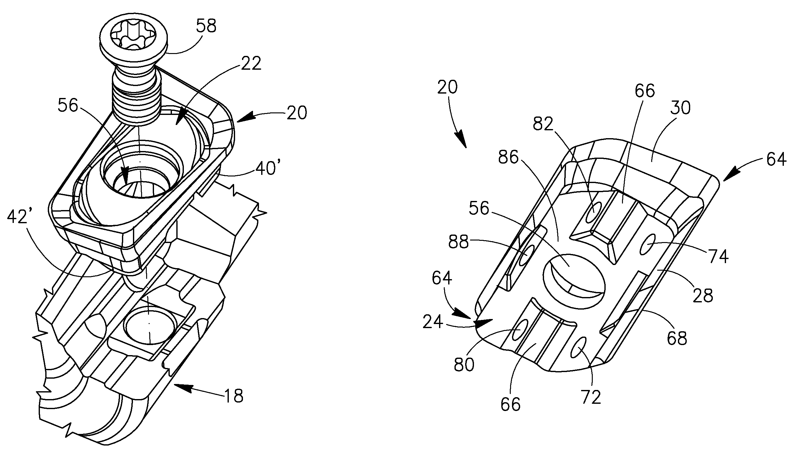
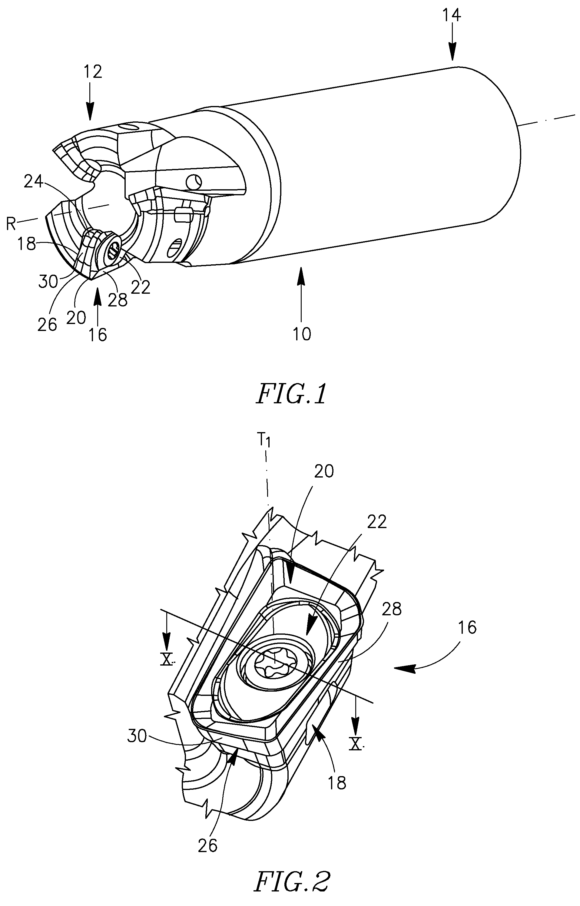
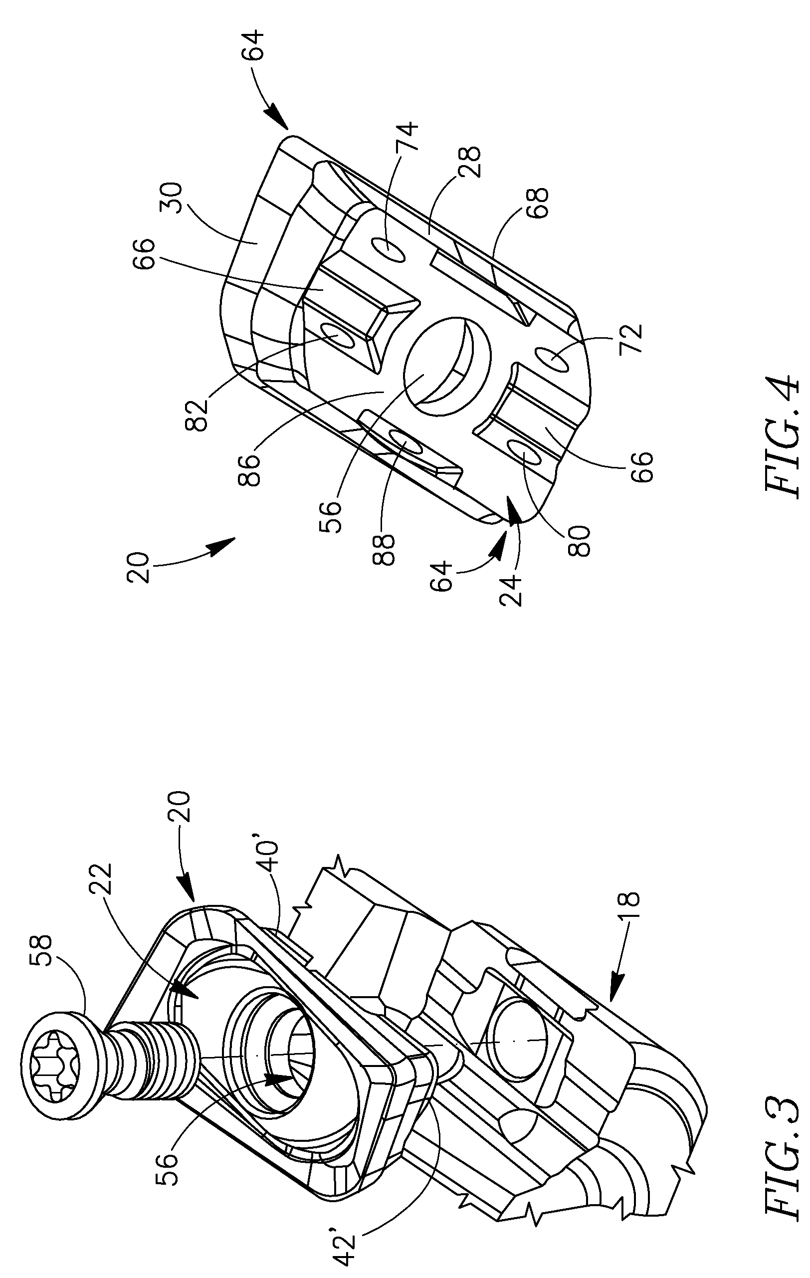
[0008]According to some embodiments of the present invention, a cutting tool is disclosed, having at least one cutting portion that includes an insert pocket, the insert pocket having a cutting insert releasably retained therein. A bottom surface of the cutting insert and a corresponding attachment surface of the insert pocket are generally complimentarily shaped, to achieve a force-withstanding, secure engagement between the surfaces, and thus provide the cutting insert with high resistance to exertion of external forces such as centrifugal or other forces exerted thereon, e.g., during operation of the cutting tool.
[0009]The disclosed means of engagement between the bottom and attachment surfaces do not over-constrain the placement of the cutting insert in the insert pocket, and therefore additionally provide accurate and convenient securing of the cutting insert in the insert pocket. For example, ordinary imperfections in the manufacturing of the bottom and attachment surfaces do not affect the accuracy or the strength of the engagement between the two surfaces, and therefore the cutting insert and tool therefor are relatively inexpensive to manufacture, e.g., by virtue of omitting the requirement to extensively grind and finish the two engaging surfaces.
[0010]In some embodiments, due to the provided engagement of the bottom and attachment surfaces, the cutting insert is not required to engage a major wall of the insert pocket, i.e., since the engagement means provide the cutting insert with satisfactory engagement, e.g., in the radial direction. The obtained engagement between the bottom and attachment surfaces may additionally allow a through-bore, formed in the cutting insert, and a threaded bore, formed in the insert pocket, both receiving a clamping screw therein to be substantially concentric, or almost concentric, therewith. This may allow the clamping screw to be exposed to a relatively small clamping pressure when received in the threaded bore, and thus withstand relatively large external forces exerted thereon.

Problems solved by technology

In many metal cutting operations and specifically, in metal cutting operations involving high speed milling or in other intensive cutting operations, the clamping screw may be exposed to large forces.
These large forces, especially if exerted for extended periods of time, risk deforming and eventually breaking the clamping screw, e.g., by tearing the screw-head away from the clamping screw body, or by breaking the clamping screw body in two—and thereby separating the cutting insert from the insert pocket.
In attempt to prevent this, for example, some rotary cutting tools are deliberately limited to a relatively low rotation rate, which may lead to a limited performance of the cutting tools.
An additional disadvantage arises in some clamping mechanisms, in which the threaded bore and through-bore are manufactured to be eccentric to one another in order to force the cutting insert against supporting surfaces of the insert pocket upon fastening of the clamping screw.
In some cutting tools using these clamping mechanisms, the eccentricity of the through-bore and threaded bore leads to unnecessary exertion of pressure on various parts of the clamping screw, thus weakening the clamping screw and decreasing the amount of externally exerted force that the clamping screw can withstand.
Therefore, some cutting tools that include these engagement means are expensive to manufacture, while in some others the cutting inserts are poorly positioned in their respective insert pockets.

Method used


Image

  • Cutting tool and cutting insert therefor
  • Cutting tool and cutting insert therefor
  • Cutting tool and cutting insert therefor

Examples


Embodiment Construction

[0030]In the following description, various aspects of the present invention will be described. For purposes of explanation, specific configurations and details are set forth in order to provide a thorough understanding of the present invention. However, it will also be apparent to one skilled in the art that the present invention may be practiced without the specific details presented herein. Furthermore, well-known features may be omitted or simplified in order not to obscure the present invention.

[0031]Although some drawings herein show, and / or some descriptions herein refer to a rotating cutting tool such as a milling tool, the present invention is not limited in this respect. For example, some embodiments of the invention may refer to a plurality of other cutting tools e.g., to various other rotating tools such as drilling tools, reaming tools or the like, or to turning tools, or to any other metal cutting tool that include one or more releasably retained cutting inserts.

[0032]...


PUM

PropertyMeasurementUnit
obtuse angleaaaaaaaaaa
acute angleaaaaaaaaaa

Abstract

A cutting tool includes one or more cutting portions, each including an insert pocket having a cutting insert releasably retained therein. The cutting insert has a bottom surface, including a plurality of surfaces, engaging a plurality of walls of the insert pocket in a plurality of sloping and non-sloping engagement regions. These engagement means provide secure and stable clamping of the cutting insert, and prevent displacement of the cutting insert during intensive cutting operations, such as high speed milling, e.g., by significantly decreasing the force exerted on the screw that fastens the cutting insert in the insert pocket.

Description

FIELD OF THE INVENTION[0001]The present invention relates to an arrangement for securing a cutting insert to an insert pocket of a cutting tool.BACKGROUND OF THE INVENTION[0002]There are known many different ways for securing a cutting insert to an insert pocket of a cutting tool. For example, there are many known clamping mechanisms for clamping the cutting insert in the insert pocket that include a clamping screw. The clamping screw is inserted through a through-bore formed in the cutting insert, and screwably received in a threaded bore formed in the insert pocket, to clamp the cutting insert therein. In some cutting tools the clamping arrangement is ‘radial’, i.e., the rotation axis of the clamping screw is generally perpendicular to a radial plane—which is parallel to, and which extends through—the axis of rotation of the cutting tool.[0003]In many metal cutting operations and specifically, in metal cutting operations involving high speed milling or in other intensive cutting o...

Claims


Application Information

Patent Timeline
Patent Type & Authority Patents(United States)
IPC IPC(8): B23B27/16B23C5/22
CPCB23C5/109B23C5/2221B23C2200/165B23C2200/168B23C2210/168Y10T407/192Y10T407/226Y10T407/22Y10T407/1924Y10T407/23Y10T407/1936B23C5/2213
Inventor HECHT
Owner ISCAR LTD
Why Eureka
Try Eureka