Collapsible sluice box

a sluice box and hinge technology, applied in the direction of magnetic separation, gas current separation, chemistry apparatus and processes, etc., can solve the problems of reducing the area for capture, affecting the efficiency of sluice box operation, etc., to achieve the effect of limiting leakage, minimizing leakage of any water flow, and maximizing the area for captur

Inactive Publication Date: 2012-12-04
RIECK ROBERT
View PDF19 Cites 5 Cited by
  • Summary
  • Abstract
  • Description
  • Claims
  • Application Information

AI Technical Summary

Benefits of technology

[0013]Briefly, these and other objects are accomplished within the present invention by providing a set of conformingly nested U-sectioned sheet metal segments hinged in progression to each other at the corresponding overlapped corners of the vertical wall surfaces thereof for pivotal movement from a folded transport arrangement to define a common sluice trough interior upon the unfolding thereof. When thus unfolded a set of inventive conformingly mated interlocks in the overlapped bottom surface edges of each of the segments are engaged to each other, retaining the structure in its deployed form in a closely matched edge overlap that minimises leakage of any water flow conveyed through the common trough.
[0014]One, of course, would align the trough inclination so that the water flow therethrough descends from the smaller segment into the next larger segment that it is nested in, and so on, with the dimensional increments between each segment and the next determined by the sheet metal thickness thereof, while the axes of the common hinge pivots are each located for close contact of the overlapped bottom surface edges once deployed. As result a well defined edge overlap is obtained by the dimensions of each segment and their pivot axes so that a sawtooth shaped, raised deformation in the upper edge span of the smaller segment can be pivotally advanced to pass, with the aid of panel flexure, into an interlocking engagement within a conformingly shaped opening in the overlapped bottom surface edge of the bottom surface of the next larger segment. Of course, this interlock can then be conveniently released by applying manual force to produce similar panel flexing, allowing the collapse the assembly for transport.
[0015]It will be appreciated that this closely fitted arrangement of overlapped edges and the mated fit of the interlock will limit the leakage of any water flows contained in the common trough interior. Accordingly, the deployed structure can then be combined with a water conserving loop returning some of the local water into a catch basin under the outlet end of the trough to a fitted header mounted on the inlet of the smallest segment. Moreover, since the interlock engagement fixes longitudinal dimension of the edge overlap a precise positioning of a set of conformingly sized mats can be made within each segment so that upon deployment their edges abut each other at the joint both to further seal off any unwanted water loss and to maximize the area for the capture the heavier particulates carried by the water stream. This same mat positioning can then be fixed by known other hardware such as screenings and / or riffling that is useful in controlling the water flow patterns. In this manner a conveniently transported, water conserving sluice box assembly is devised in which all the cooperative components are inventively optimized for the end use intended.

Problems solved by technology

Once again, while each of these prior examples are suitable for their intended purpose, the interests of portability have often dominated the function obtained and functions like process water conservation and its recovery are rarely addressed.
Although quite effective as a collapsible sluice structure, these prior sluice arrangements are inherently prone to leakage at each of the hinged, and fastened, folds resulting in unwanted losses of the water stream, and with it also the losses of the heavier matter that may have been collected at the hinge.
Moreover, the inherently imprecise nature of a threaded fastener enabled process has invariably resulted in large overlapping gaps at each hinged joint and the resulting water leakages precluding any realistic conservation of these early water flows and its recirculation.

Method used


Image

  • Collapsible sluice box
  • Collapsible sluice box
  • Collapsible sluice box

Examples


Embodiment Construction

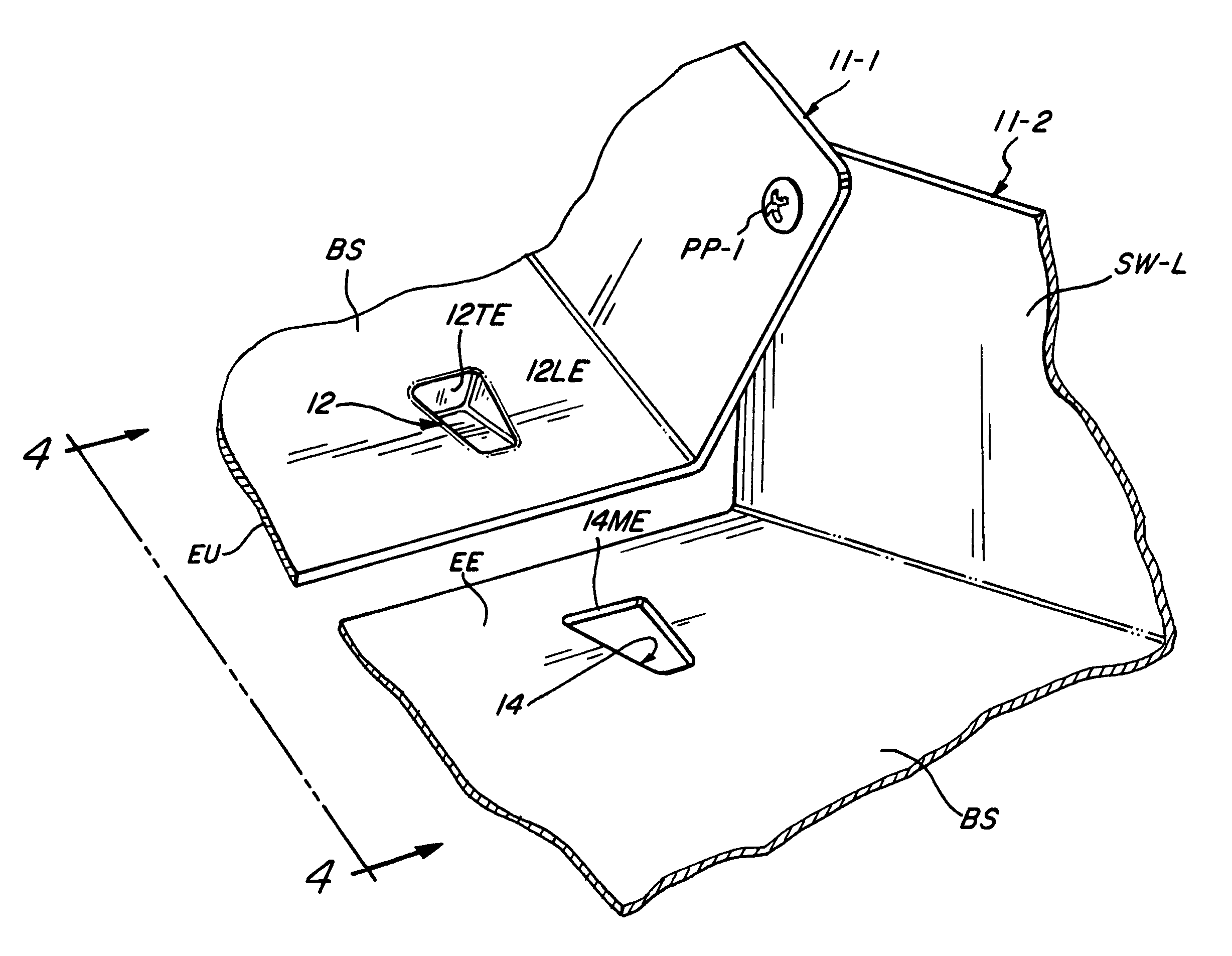
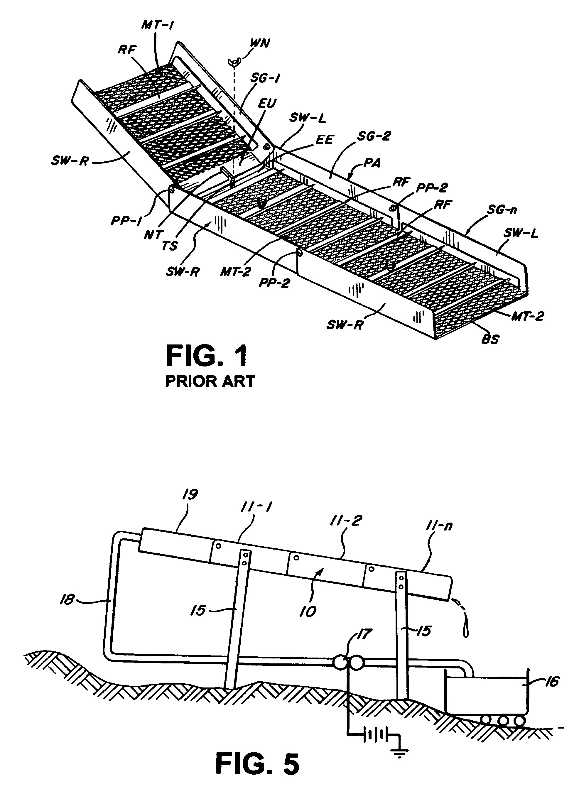
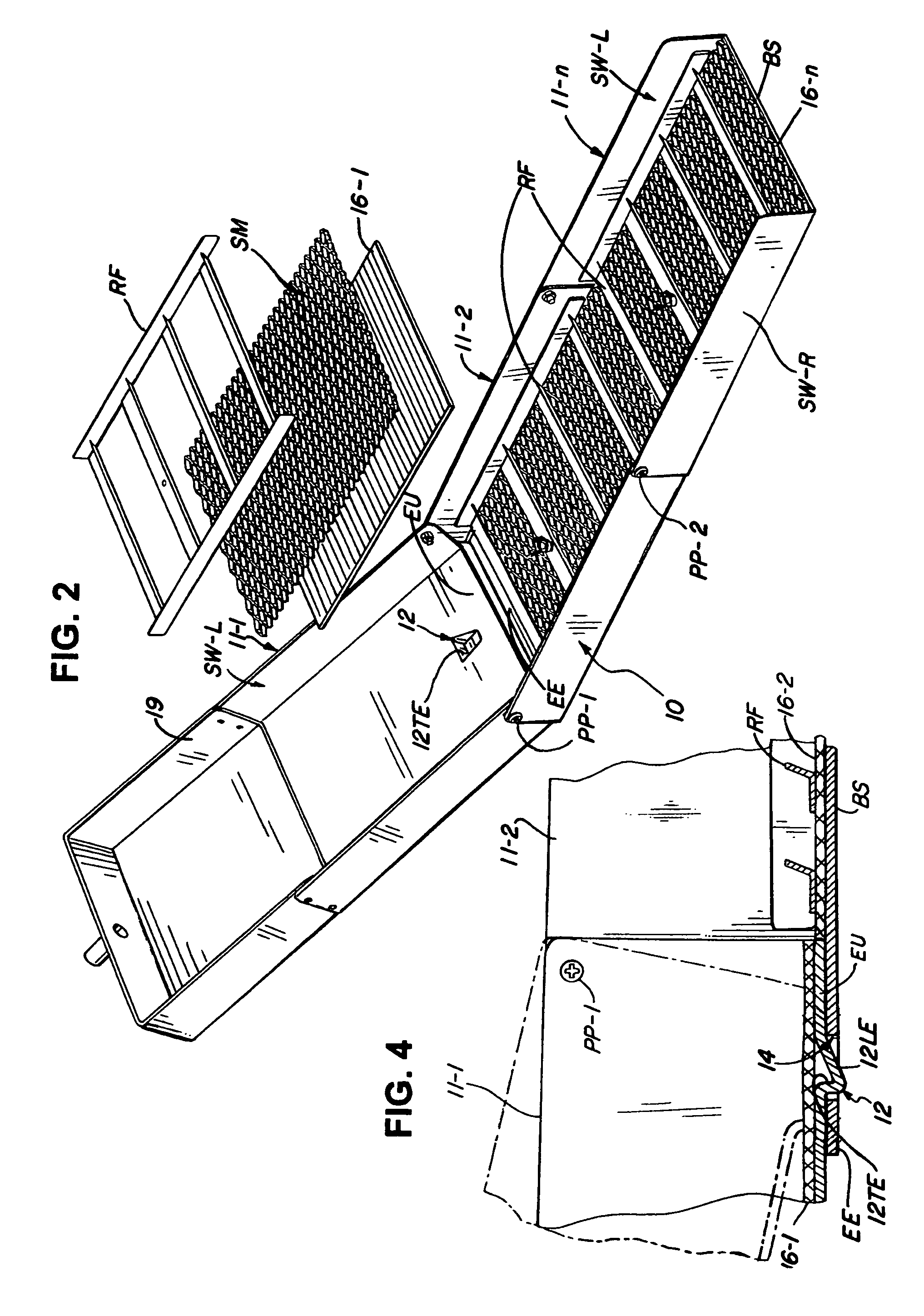
[0021]As shown in FIG. 1 the typical prior art implementation of a collapsible sluice box assembly PA, as exemplified by the structure sold by JOBE Wholesale under their model number 6506, is generally defined by a set of nested U-sectioned sheet metal segments SG-1, SG-2 through SG-n each including a rectangular bottom surface BS bounded on both its longitudinal edges by a corresponding vertically aligned left and right sidewall SW-L and SW-R. In order to accommodate a nested receipt of one of the segments in the next adjacent one they are each incrementally larger by at least the thickness of the sheet metal stock with one end of the side walls SW-R and SW-L of the first segment SG-1 pinned by pivot pins PP-1 to the correspondingly overlapping edges of the next segment SG-2, with segment SG-2 then pinned by pivot pins PP-2 to the next segment, and so on.

[0022]In each instance the pivot axes of pins PP-1, PP-2 through PP-n are separated from the corresponding bottom surfaces BS by ...


PUM


Abstract

A folding sluice box assembly includes a plurality of generally U-sectioned trough segments having their end portions nested in size progression and hinged to each other to form an overlap of the received portion and the receiving portion. A deformation in the bottom surface of a received portion is aligned on full pivotal extension for mating receipt in a conforming bottom surface opening in the receiving portion, thus interlocking of the assembly into its working configuration. When thus extended the edge of a resilient mat positioned on the bottom surface of the receiving segment abuts the edge of the received segment to effect a substantial seal therewith.

Description

REFERENCE TO RELATED APPLICATIONS[0001]This application obtains the benefit of the earlier filing date of U.S. Provisional Application Ser. No. 61 / 398,943 filed on Jul. 2, 2010.BACKGROUND OF THE INVENTION[0002]1. Field of the Invention[0003]The present invention relates to placer mining devices, and more particularly to a hinged sluice box structure that is collapsible for easy transport to be thereafter erected on site into its operative deployment by interlocks that render this deployment convenient while also minimizing leakage losses of the contained water flow in the course of its use.[0004]2. Description of the Prior Art[0005]The mining of gold or other precious metals aggregated in alluvial deposits, known generally as placer mining, has been practiced by man since the dawn of time, most often by water irrigated methods suggested by the alluvial aggregation itself. While quite effective in using water flow for segregating the heavier precious metal components from the rest of...

Claims


Application Information

Patent Timeline
Patent Type & Authority Patents(United States)
IPC IPC(8): B03C1/30B03B7/00
CPCB03B5/26
Inventor RIECK, ROBERT
Owner RIECK ROBERT
Why Eureka
Try Eureka