Plasma uniformity control using biased array

a technology of arrays and plasmas, applied in the field of plasma uniformity control, can solve the problems of difficult control of dose uniformity, inability to use plasma doping systems, and similar profile of implant profiles on workpieces, so as to improve plasma uniformity, reduce local plasma density, and better confine charged particles

Inactive Publication Date: 2012-12-11
VARIAN SEMICON EQUIP ASSOC INC
View PDF7 Cites 0 Cited by
  • Summary
  • Abstract
  • Description
  • Claims
  • Application Information

AI Technical Summary

Benefits of technology

[0012]To overcome the disadvantages of the prior art, an apparatus and method for improving the uniformity of the plasma in a plasma based system are described. The apparatus may include a plurality of electrical conductors, to which a plurality of electrical potentials can be applied. In one embodiment, the conductors are arranged in a two dimensional array. In another embodiment, the conductors are arranged as a set of concentric rings. This apparatus may be located within the plasma based system, preferably positioned above the workpiece so that the plasma is located between it and the workpiece or substrate. Alternatively, the apparatus may be located to the side of the plasma. By applying bias voltages to the one or more conductors, the plasma density may be controlled. For example, a positively bias voltage may be applied to at least one of the conductors, and one or more conductors may attract the electrons from the plasma, thereby reducing the local plasma density proximate the conductor. In contrast, a negatively bias voltage may be applied to one or more conductors and one or more conductors may confine the electrons to reshape the plasma boundary proximate one or more conductors. By properly adjusting the polarity, magnitude and duration of the bias voltages applied to one or more conductors, the ion uniformity within the plasma can be controlled.
[0013]In a further embodiment, a magnetic field is included in the same direction as the electric field created by the bias voltage so as to better confine the charged particles.

Problems solved by technology

However, the uniformity of the dose is difficult to control.
Such components, however, are not available with a plasma doping system.
As a result, implant profile on the workpiece shows a similar non-uniform profile—higher implant dose in the middle, and lower dose in the edges of the workpiece.
However, such techniques may mitigate the plasma non-uniformity, but cannot change the generic non-uniform density profile shown in FIG. 4.

Method used


Image

  • Plasma uniformity control using biased array
  • Plasma uniformity control using biased array
  • Plasma uniformity control using biased array

Examples


Embodiment Construction

[0022]Herein, several embodiments of an apparatus and method for achieving uniform plasma density are disclosed with reference to accompanying drawings. The detailed disclosure contained herein is intended for illustration, for better understanding the disclosure, and not a limitation thereto. For example, the disclosure may be made with reference to a plasma doping or a plasma immersion ion implantation system. However, the present disclosure may be equally applicable to other plasma based systems including plasma based etching and deposition systems.

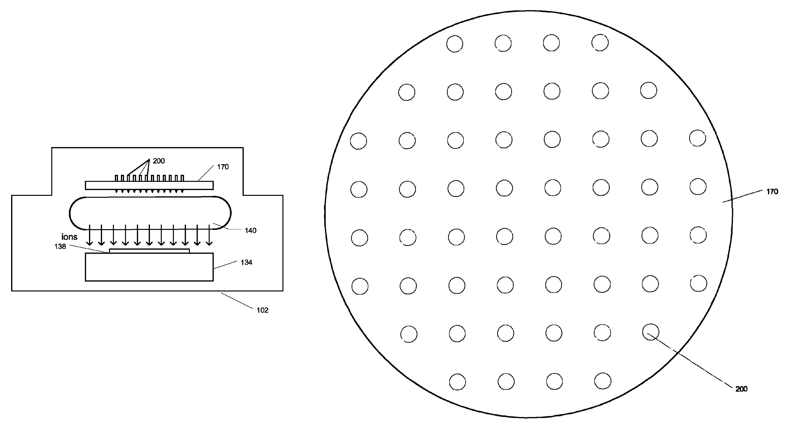
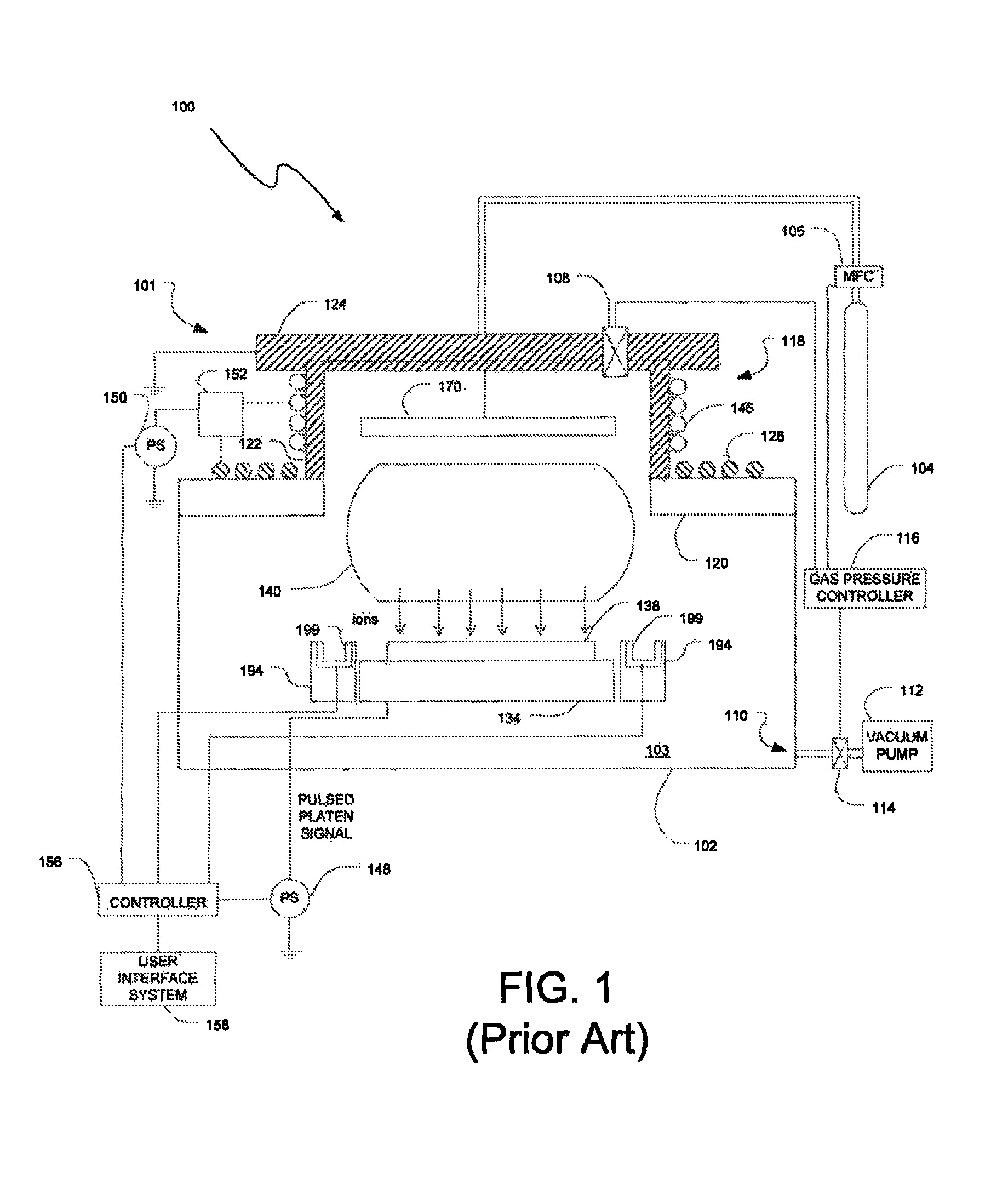
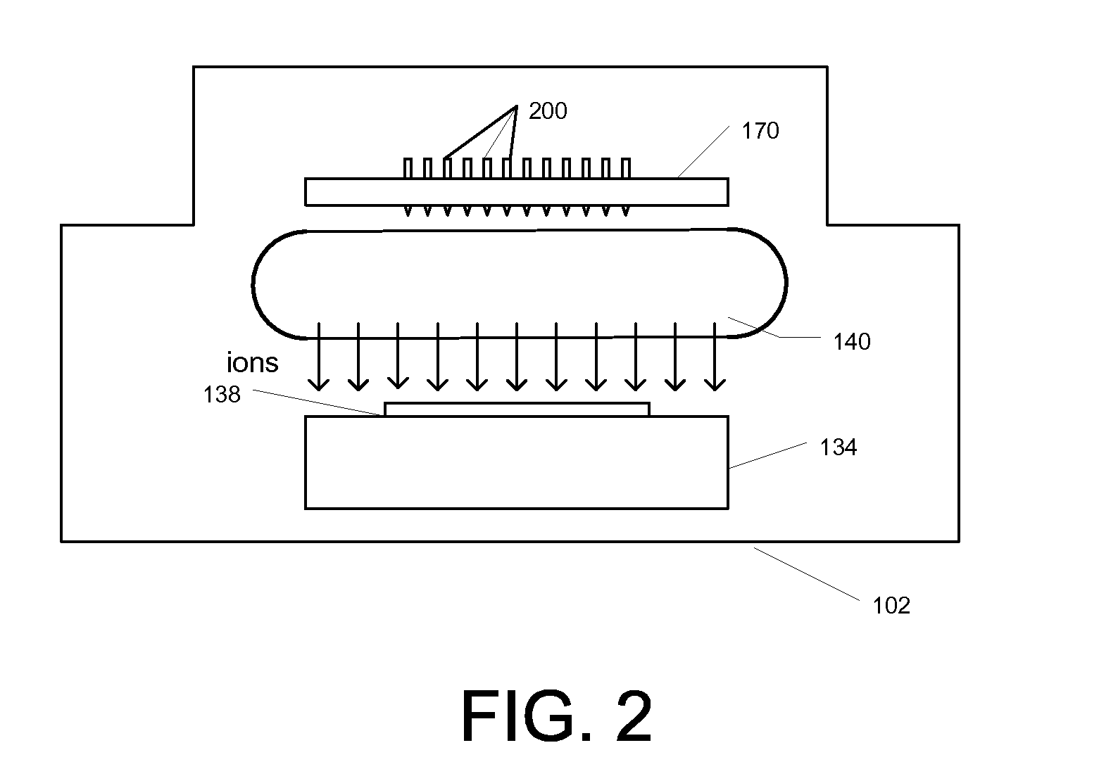
[0023]As described above, a plasma doping system is used to create a plasma in close proximity to the workpiece. The workpiece may be then biased to a certain electrical potential. However, the plasma density or the ion concentration within the generated plasma may be non-uniform. Typically, the concentration of ions is the highest near the center and lower near the chamber wall, as shown in FIG. 4.

[0024]In a plasma based system that i...


PUM

PropertyMeasurementUnit
heightaaaaaaaaaa
diameteraaaaaaaaaa
distanceaaaaaaaaaa

Abstract

Apparatus and method for improving the plasma uniformity in a plasma based system are described. The apparatus may include a plurality of electrical conductors, to which one or more types of electrical potentials may be applied. The conductors may be arranged in an array and may preferably be positioned near the plasma. By applying the bias voltages to the various electrically conductors, the plasma can be manipulated. For example, the conductors may extract or confine the electrons in the plasma, thereby locally adjusting the plasma density near the conductors. In the process, uniformity of the plasma density or ion concentration in the plasma may be improved. In a further embodiment, a magnetic field is included in the same direction as the electric field created by the bias voltage so as to better confine the charged particles.

Description

BACKGROUND OF THE INVENTION[0001]Ions are commonly implanted into a substrate in ion implantation processes to produce semiconductor devices. These ion implantations may be achieved in a number of different ways. For example, a beam-line ion implantation system may be used to perform the ion implantation process. In the beam-line ion implantation system, an ion source is used to generate ions, which are manipulated in a beam-like state, and then directed toward the wafer. As the ions strike the wafer, they dope a particular region of the wafer. The configuration of doped regions defines their functionality, and through the use of conductive interconnects, these wafers can be transformed into complex circuits.[0002]In another example, a plasma containing ions may be generated near the substrate. A voltage is then applied to the substrate to attract ions toward the substrate. This technique is known as plasma doping (“PLAD”) or plasma immersion ion implantation (“PIII”) process. FIG. ...

Claims


Application Information

Patent Timeline
Patent Type & Authority Patents(United States)
IPC IPC(8): C03C15/00
CPCC23C14/48G21K5/02H01J37/32412H01J37/32623H01J37/32706
Inventor KOO, BON-WOONG
Owner VARIAN SEMICON EQUIP ASSOC INC
Why Eureka
Try Eureka