
System and method for purification of flue gases

a technology of flue gas and purification method, which is applied in the direction of hydrogen sulfide, separation process, sulfur compound, etc., can solve the problems of not always being able to adjust the ph of the absorption suspension, the inability to achieve the desired degree of precipitation and the desired measure of dust removal with all the known methods, and the high cost of the absorption agent used. cost

Active Publication Date: 2012-12-25
BABCOCK NOELL GMBH
View PDF30 Cites 15 Cited by
  • Summary
  • Abstract
  • Description
  • Claims
  • Application Information

AI Technical Summary

Benefits of technology

[0030]Proceeding from a system for purification of flue gases from power plants that work with fossil fuels, according to the oxyfuel process, which consists of multiple absorption stages, and a method for purification of flue gas, it is an object of the invention to remove and avoid contaminants of the CO2-rich gas from the oxyfuel process, for one thing by means of efficient precipitation of the concentrated harmful gases and harmful substances from the flue gas, and for another, by means of avoiding the feed of air as contaminants of the CO2-rich gas into the harmful gas absorption stage. An oxidation air minimization should be achieved by means of oxidation at optimal pH values in the suspension, and better and more cost-advantageous flue gas purification should be achieved by means of an improved process management.
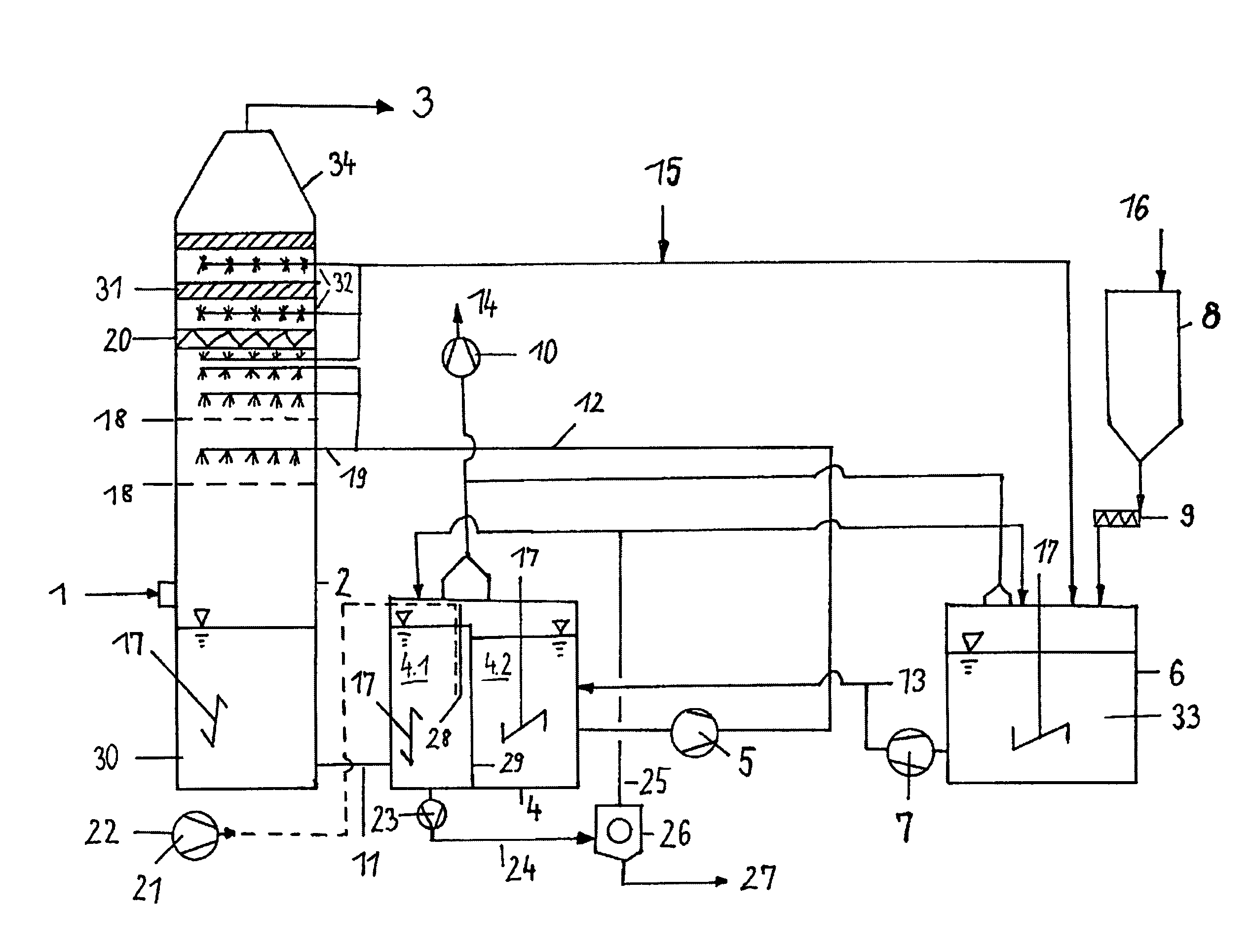
[0047]It is advantageous if the contact installations represent one perforated metal sheet or multiple, preferably two, perforated metal sheets. Dust precipitation in the absorber or spray tower is improved by means of the perforated metal sheets, because the flue gas velocity in the bores of the perforated metal sheets is significantly higher than the speed in front of the spraying levels.
[0049]A corresponding dimensioning of the connection line between absorber and reaction container prevents undesirable gas back-flow and thus contamination of the CO2-rich gas by means of air entry into the absorber. This arrangement represents a simple sealing possibility, by means of targeted discharge of suspension into the reaction container. Oxidation of the calcium sulfite to produce gypsum takes place by means of the introduction of the oxidation air into the absorption suspension, and driving out CO2 by means of the air ensures optimal limestone solubility in the second chamber of the reaction container. For better mixing, it is advantageous to provide a stirrer, for example a slanted stirrer. Because the suspension is not enriched with limestone, it has a lower pH than the suspension in the second reaction chamber. This difference in pH is advantageous, because suspension for a solid / liquid separation is drawn off at the bottom of the first reaction chamber, by way of a pump, which separation should advantageously take place in a hydrocyclone.
[0053]According to the invention, the CO2 that has formed in the reaction container and the excess oxidation air in the reaction container are separately removed from the process, and therefore contamination of the CO2-rich gas is avoided in the oxyfuel process. As a result, gastight separation of flue gas and oxidation air is also achieved. This separation and removal can advantageously take place by way of an exhaust vapor hood. The gas drawn off can be passed to purification separately. It is advantageous to also use the exhaust vapor hood to draw off the gases that form in the lime / limestone suspension container. The limestone suspension container serves to produce a limestone suspension. Lime / limestone meal is introduced into the process fluid from a supply container, preferably a silo having a metering device. A screw conveyor is suitable as a metering device. It is advantageous if a stirring mechanism is disposed in the lime / limestone suspension container, which assures thorough mixing of lime / limestone meal and process water without upper run. The limestone suspension is conveyed into the second chamber of the reaction container by means of a limestone suspension pump.
[0057]A uniform velocity distribution is achieved, already ahead of the spraying levels, by the use of the perforated metal sheet as a contact installation or multiple perforated metal sheets disposed one behind the other for flue gas purification. To the sheet or sheets suspension is applied from the spraying levels that lie above the sheet or sheets. This structure of the absorber makes it possible to achieve precipitation degrees of over 99% even at high sulfur dioxide contents.

Problems solved by technology

The absorption agent used is very expensive in comparison with limestone suspension / lime slurry.
It is a further disadvantage of this system that multiple separate containers are needed for treatment, which are supplied with a partial suspension stream by way of pumps.
A further disadvantage of this prior art is that in both vessels, no feed of oxidation air, for example via a lance, and no exhaust vapor removal are provided, and that the absorption tower functions according to the same-current principle.
Furthermore, it is generally not always possible to adjust the pH of the absorption suspension in such a manner that it achieves a maximal effect in the purification process.
Furthermore, the desired degree of precipitation and the desired measure of dust removal cannot be achieved with all the known methods.

Method used


Image

  • System and method for purification of flue gases
  • System and method for purification of flue gases

Examples


Embodiment Construction

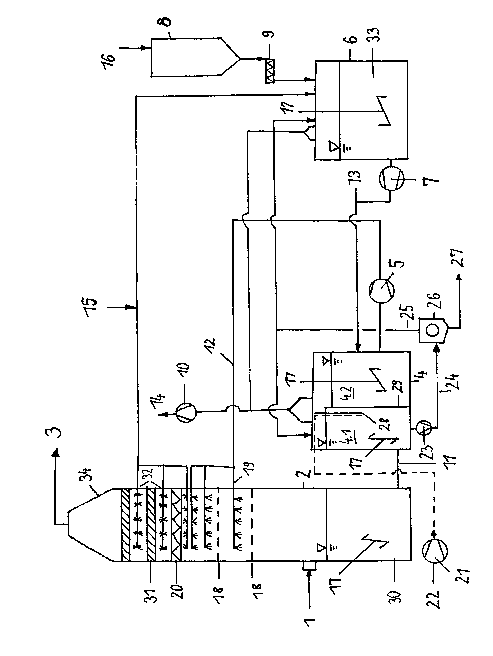
[0064]The system for purification of flue gas from fossil fuels, according to the invention, consists essentially of an absorber 2, the correspondingly dimensioned connection line to the reaction container, the reaction container 4, consisting of two chambers 4.1, 4.2, next to which a lime or limestone suspension container 6 is situated, on the same level, above which a lime or limestone silo 8 for lime or limestone meal 16 is disposed, whereby the metering device 9, a metering screw, meters lime or limestone meal 16 into the limestone suspension container 6. Process water 15 is introduced into the container, and the stirring mechanism 17 ensures uniform, thorough mixing. A line that forms the inflow 24 to the hydrocyclone leads from first chamber 4.1 of reaction container 4 to the hydrocyclone 26, with which gypsum suspension 27 is precipitated. The thin-liquid suspension is pumped back to first chamber 4.1 or to lime or limestone suspension container 6 in lines 25 for the upper ru...


PUM

PropertyMeasurementUnit
energyaaaaaaaaaa
distanceaaaaaaaaaa
structureaaaaaaaaaa

Abstract

A method and system for purifying flue gases from power plants fired with fossil fuels has an absorber with at least one contact installation level arranged in an upper region, impinged with a suspension, and flowed through by untreated gas. The lower region has an absorption suspension sump, above which the inflow for the untreated gas is disposed. A separate reaction container includes two chambers separated by a partition wall with an overflow. The first chamber is connected with the sump, receives oxidation air, and has in a lower region an opening for discharging suspension. The second chamber is connected with a lime / limestone suspension container. A gas exhaust hood above the reaction container draws exhaust vapors into an exhaust vapor hood. A line for absorption suspension extends between at least one spraying level of the absorber and the reaction container, and a process water feed lies above the spraying level.

Description

CROSS REFERENCE TO RELATED APPLICATIONS[0001]Applicants claim priority under 35 U.S.C. §119 of German Application No. 10 2007 050 904.0 filed Oct. 23, 2007. Applicants also claim priority under 35 U.S.C. §120 of International Application No. PCT / DE2008 / 001605 filed Oct. 6, 2008. This application is a by-pass continuation application of said International Application No. PCT / DE2008 / 001605 filed Oct. 6, 2008. The International Application under PCT Article 21(2) was not published in English. The disclosure of the aforesaid International application and German application are incorporated by reference.BACKGROUND OF THE INVENTION[0002]1. Field of the Invention[0003]The invention relates to a system and a method for purification of flue gases from power plants that work with fossil fuels, according to the oxyfuel process, and for retrofitting of power plants for preparation of the inclusion of a CO2 absorption stage (post combustion).[0004]2. The Prior Art[0005]Various methods and system...

Claims


Application Information

Patent Timeline
Patent Type & Authority Patents(United States)
IPC IPC(8): B01D47/00B01D50/00
CPCB01D53/501B01D53/504B01D2257/504
Inventor WELP, HELMUTSCHMIDT, THOMAS
Owner BABCOCK NOELL GMBH
Learn More