Piston compressor, particularly refrigerant compressor

a compressor and compressor technology, applied in the field of compressors, can solve the problems of carrier plates, low efficiency, and relative thinness, and achieve the effect of low cost and good efficiency

Inactive Publication Date: 2013-01-01
DANFOSS AS
View PDF8 Cites 0 Cited by
  • Summary
  • Abstract
  • Description
  • Claims
  • Application Information

AI Technical Summary

Benefits of technology

[0008]With this embodiment, one single plate will be sufficient, namely the carrier plate. Additional plates can be saved, so that the manufacturing costs can be reduced. On the one hand, this occurs through a smaller material consumption and secondly in that only one carrier plate has to be handled during the assembly of the cylinder head. Further, the carrier plate can be made relatively thin, that is, a carrier plate can be used, which does not have natural stability. On the contrary, the stability of the valve plate arrangement does not occur until the carrier plate is connected to the mechanically sufficiently stable valve cover. However, this connection does not only have the task of ensuring a mechanical reinforcement for the carrier plate. It also has the additional task of providing a gas-tight separation between the suction area and the pressure area on the one side and between the pressure area and the environment on the other side. The connection seam can, for example, be made by welding, soldering or gluing. Thus, a sealing between the carrier plate and the valve cover is saved, which contributes to a further cost reduction. As the carrier plate can be made very thin, a relatively small harmful space occurs, which is particularly important in connection with low-temperature compressors. The small thickness of the carrier plate also results in small pressure losses during the flow of the refrigerant gas through the suction and pressure valves. Further, a working of the surface of the carrier plate can be avoided, at least in large areas.
[0009]Preferably, the suction valve has a suction valve element that is located on one side of the carrier plate, and the pressure valve has a pressure valve element that is located on the other side of the carrier plate. The use of suction and pressure valve elements separated by the carrier plate has the advantage that these valve elements can be worked independently of the carrier plate. In particular, it is much easier to provide the valve elements with an edge rounding, which contributes to a long life. This is possible, as, before the assembly of the valve arrangement, the valve elements are accessible from all sides. The valve elements require no additional plate, through which the gas to be compressed would then have to flow.
[0011]Preferably, the suction valve element and the pressure valve element are made in the form of fins. These fins are fixed unilaterally, that is, with one end, to the carrier plate and can lift off from the carrier plate with the other end to release a suction opening or a pressure opening. As only the suction valve element and the pressure valve element have to be made of relatively expensive valve material, for example laminar valve steel, the material costs are low.
[0012]Preferably, a sealing is arranged between the cylinder head and the compressor block. The sealing provides tightness between the cylinder head and the compressor block. At least in the area, in which the sealing is located, an expensive working or a grinding of the surface of the carrier plate is not required. Here, the carrier plate can still have a certain roughness, as here the sealing rests. On the side next to the valve cover the carrier plate can also have a certain roughness, as here the tightness is provided by the connection seam or the connection seams.
[0013]Preferably, the sealing acts upon the suction valve element with a restoring force. Thus, the sealing does not only assume the task of sealing the compression chamber towards the environment, but also the task of quickly restoring the suction valve element after finishing the suction stroke, thus closing the suction valve. An additional spring component can be saved.

Problems solved by technology

On the one hand, this occurs through a smaller material consumption and secondly in that only one carrier plate has to be handled during the assembly of the cylinder head.
Further, the carrier plate can be made relatively thin, that is, a carrier plate can be used, which does not have natural stability.
However, this connection does not only have the task of ensuring a mechanical reinforcement for the carrier plate.
As the carrier plate can be made very thin, a relatively small harmful space occurs, which is particularly important in connection with low-temperature compressors.
The small thickness of the carrier plate also results in small pressure losses during the flow of the refrigerant gas through the suction and pressure valves.

Method used


Image

  • Piston compressor, particularly refrigerant compressor
  • Piston compressor, particularly refrigerant compressor
  • Piston compressor, particularly refrigerant compressor

Examples


Embodiment Construction

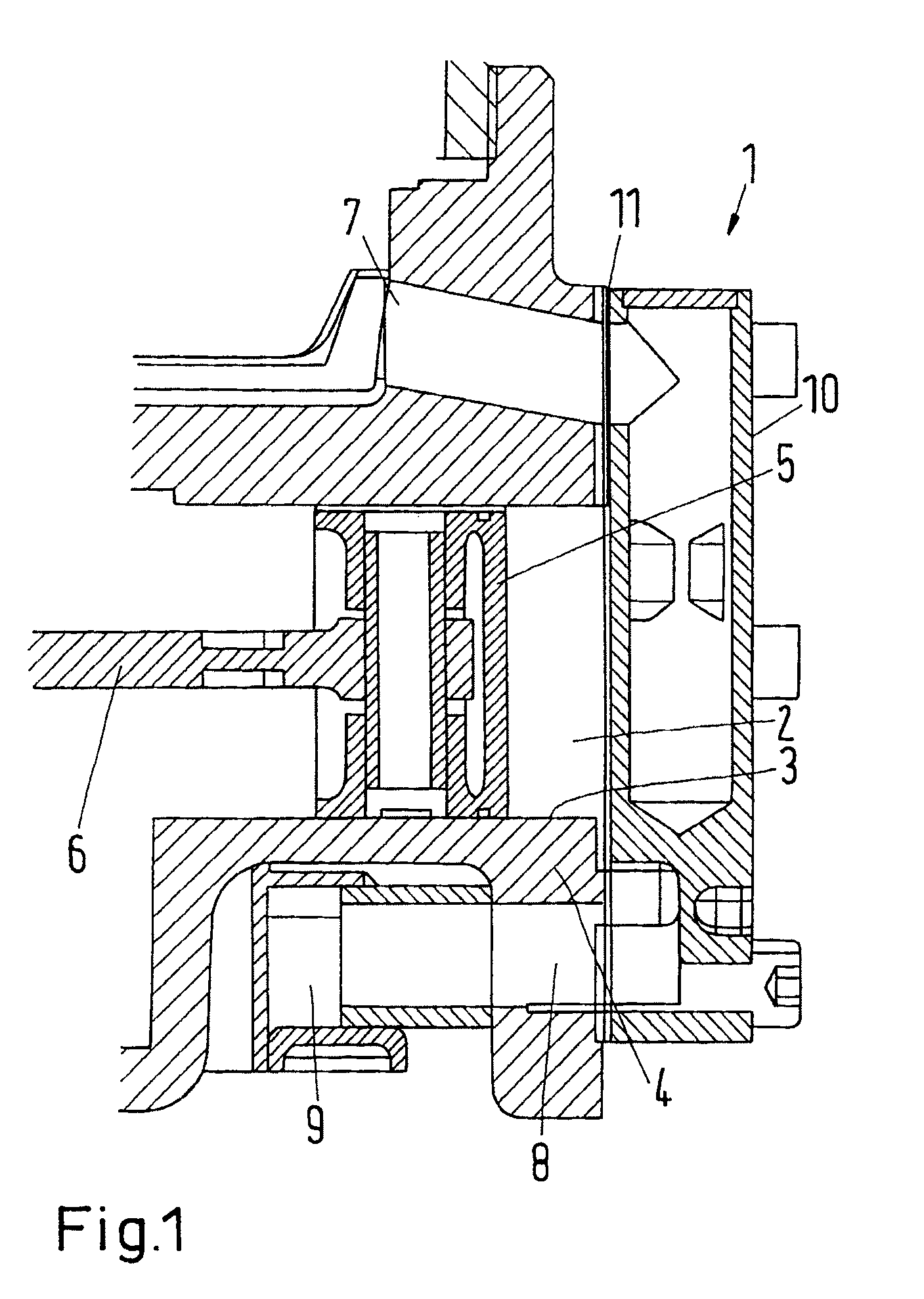
[0022]FIG. 1 is a schematic view of a refrigerant compressor 1 with a compression chamber 2 formed in a cylinder 3. The cylinder 3 is located in a compressor block 4. The volume of the compression chamber 2 can be changed by means of a piston 5, a drive, not shown in detail, driving the piston 5 to reciprocate via a connecting rod 6.

[0023]The cylinder block 4 is located in a suction channel 7, via which refrigerant gas can be sucked into the compression chamber 2. A pressure channel 8 is partly guided through the compressor block 4 and supplies compressed refrigerant gas to a pressure gas collector 9.

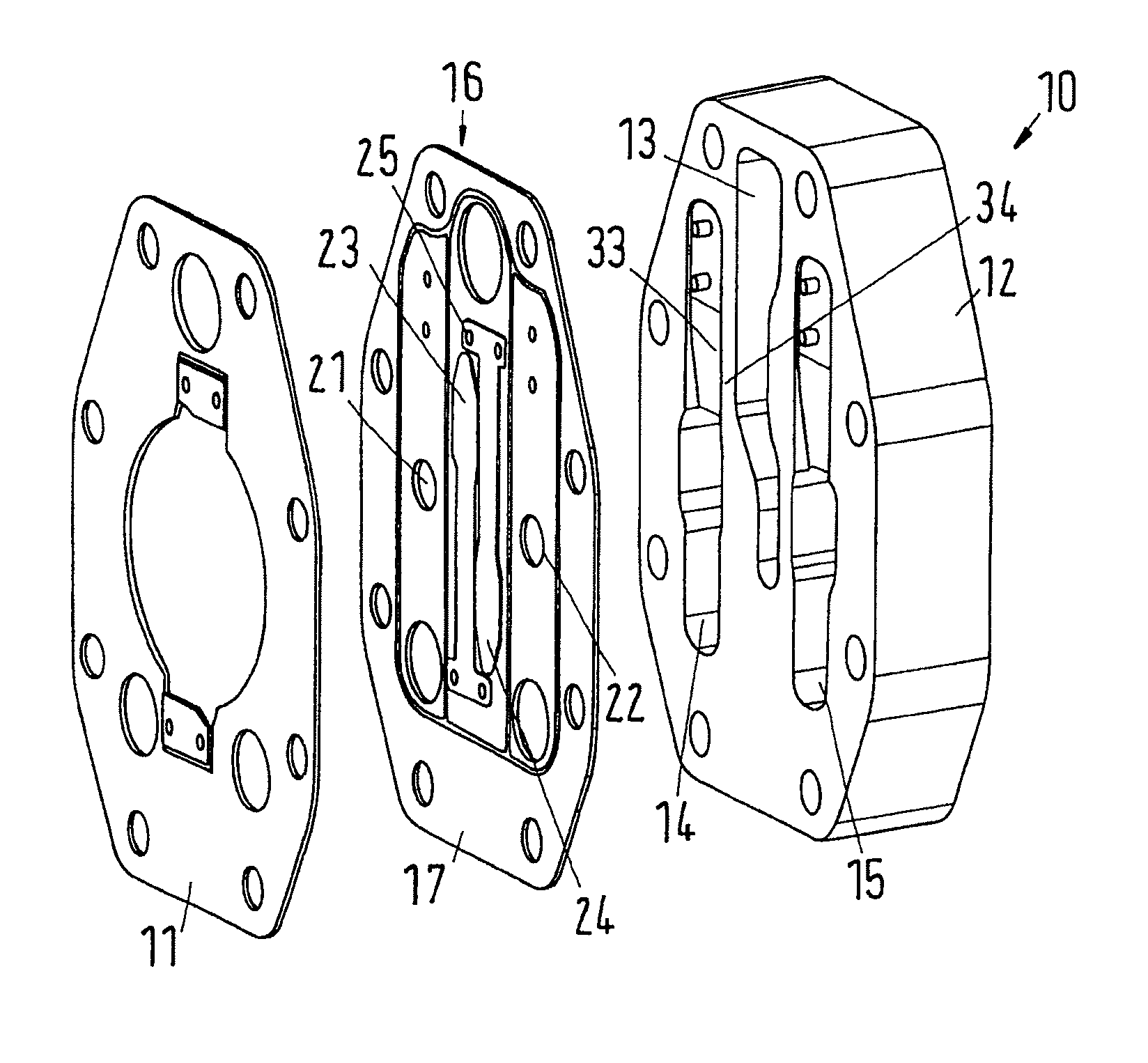
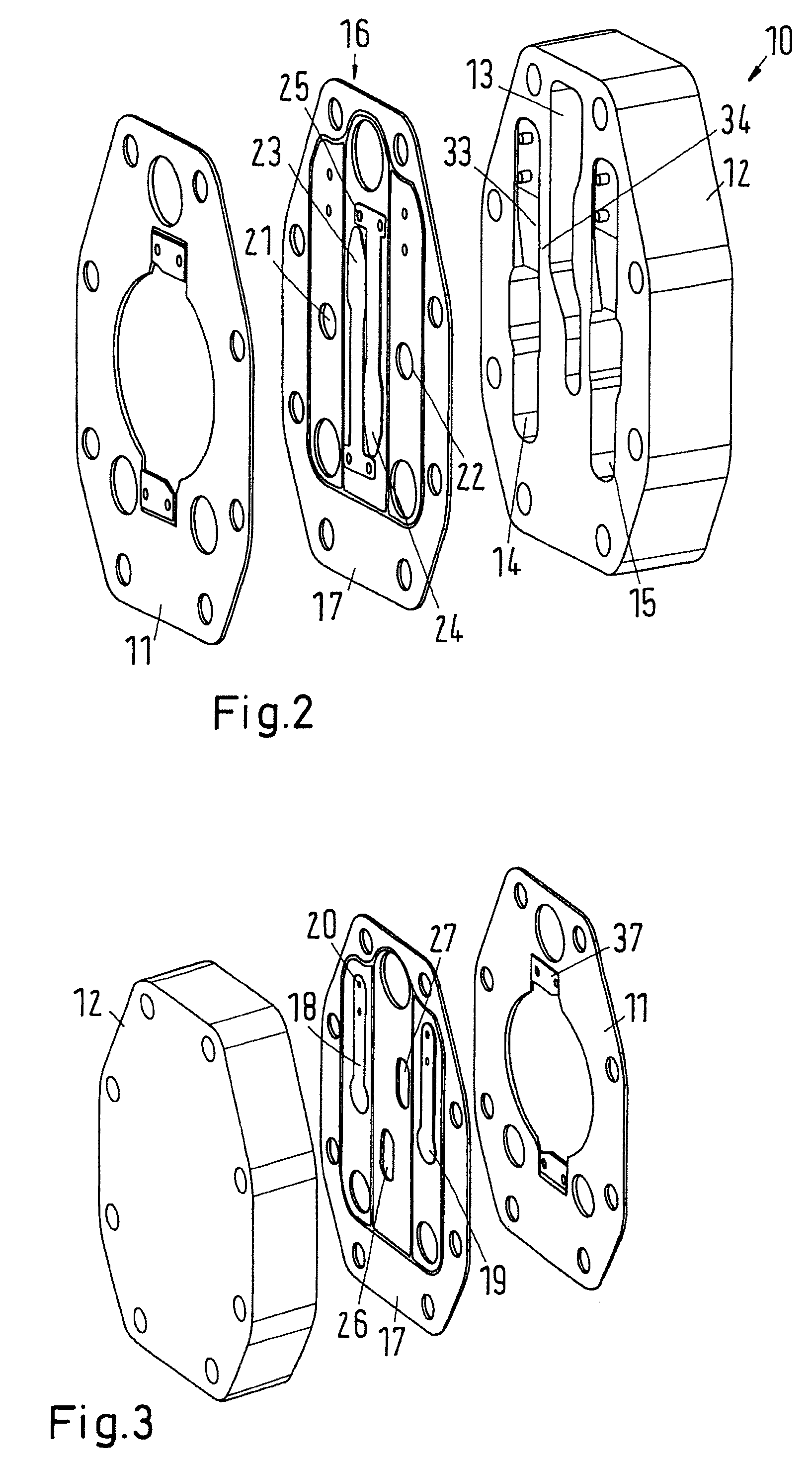
[0024]A cylinder head 10 closes the compression chamber 2 at the front side of the cylinder 3. Between the cylinder head 10 and the compressor block 4 a sealing 11 is located. In the following, the cylinder head 10 is explained in detail by means of the FIGS. 2 to 5.

[0025]The cylinder head 10 has a valve cover 12, in which a suction gas channel 13 and two pressure gas channels 14, 15 ar...


PUM


Abstract

A piston compressor, particularly a refrigerant compressor includes a compression chamber in a compressor block, the compression chamber being delimited by a cylinder head (10), the cylinder head (10) comprising at least one valve plate arrangement with at least one suction valve (23, 24) and at least one pressure valve (21, 22), as well as a valve cover (12). To achieve low manufacturing costs, though maintaining a good efficiency, the valve plate arrangement (16) is formed by a carrier plate (17) that comprises the suction valve (23, 24, 26, 27) and the pressure valve (18, 19, 21, 22) and is connected by at least one gas-tight connection seam (28, 31) to the valve cover (12), the connection seam (28, 31) separating a suction area (32) and a pressure area (29, 30) from one another and sealing at least the pressure area (29, 30) towards the outside.

Description

CROSS REFERENCE TO RELATED APPLICATION[0001]Applicant hereby claims foreign priority benefits under U.S.C. §119 from German Patent Application No. 10 2008 037 672.8 filed on Aug. 14, 2008, the contents of which are incorporated by reference herein.FIELD OF THE INVENTION[0002]The invention concerns a piston compressor, particularly a refrigerant compressor with a compression chamber in a compressor block, the compression chamber being delimited by a cylinder head, the cylinder head comprising at least one valve plate arrangement with at least one suction valve and at least one pressure valve, as well as a valve cover.BACKGROUND OF THE INVENTION[0003]Such a piston compressor is, for example, known from DE 10 2004 047 159 B4. The valve plate arrangement comprises a pressure valve plate and a suction valve plate. The pressure valve plate and the suction valve plate are connected to each other and the valve cover by welding. The pressure valve plate has several pressure valve elements, w...

Claims


Application Information

Patent Timeline
Patent Type & Authority Patents(United States)
IPC IPC(8): F04B39/10F04B53/10
CPCF04B39/1073Y10T137/7892Y10T137/6086
Inventor SUSS, JURGENJEPSEN, CHRISTIAN
Owner DANFOSS AS
Why Eureka
Try Eureka