
Power-split wind power generator gearbox

Inactive Publication Date: 2013-01-01
ZF FRIEDRICHSHAFEN AG
View PDF17 Cites 7 Cited by
  • Summary
  • Abstract
  • Description
  • Claims
  • Application Information

AI Technical Summary

Benefits of technology

The present invention provides a wind turbine generator system with a rotor directly coupled to the wind turbine transmission for higher power output. The design includes a compact integrated large roller bearing and a cardan-type decoupling unit to minimize wear and tear. The torque flow is directed through at least two planetary stages for power distribution, with the two planetary stages coupled via a sun gear shaft. A hollow shaft is used to transfer the torque from the second planetary stage to the first. Overall, this design achieves a compact structure with minimal wear and tear.

Problems solved by technology

This requirement is in conflict, however, with the tendency towards ever larger wind turbine generator systems having greater power, which require more powerful transmissions, among other things.
Limiting this construction to a normal shaft as a drive shaft on the transmission input side leads to the problem, however—should the rotor be attached directly to the wind turbine transmission—that the relatively large diameter of a rotor hub must be connected to the small diameter of the drive shaft.
The rotor of a wind turbine generator system does not only produce a pure torque, however.
Due to its own weight forces and due to force and moment variations on the rotor blade caused by the wind and the like, the drive shaft is exposed, in particular, to disturbing bending moments and transverse forces.
Apart from extreme bearing loads at the drive shaft, they can also lead to disturbances in tooth mesh in the transmission and therefore to higher wear and tear.
While in this technical approach, due to its construction, the disturbing bending moments and transverse forces are weakened due to feeding the power onto a large diameter, they are not, however, entirely eliminated so that the disturbing deformation of the components situated in the power flow also affects the toothing between the planetary gears and the hollow and sun gears via the planet carrier.

Method used


Image

  • Power-split wind power generator gearbox
  • Power-split wind power generator gearbox
  • Power-split wind power generator gearbox

Examples


Embodiment Construction

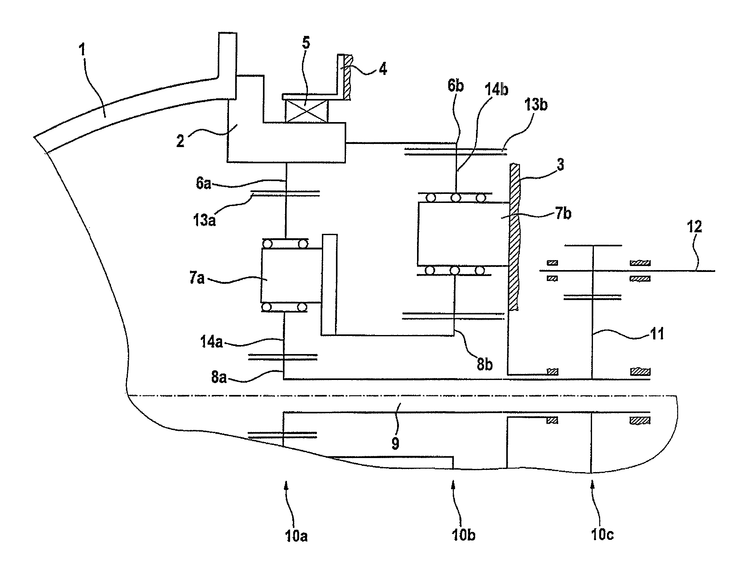
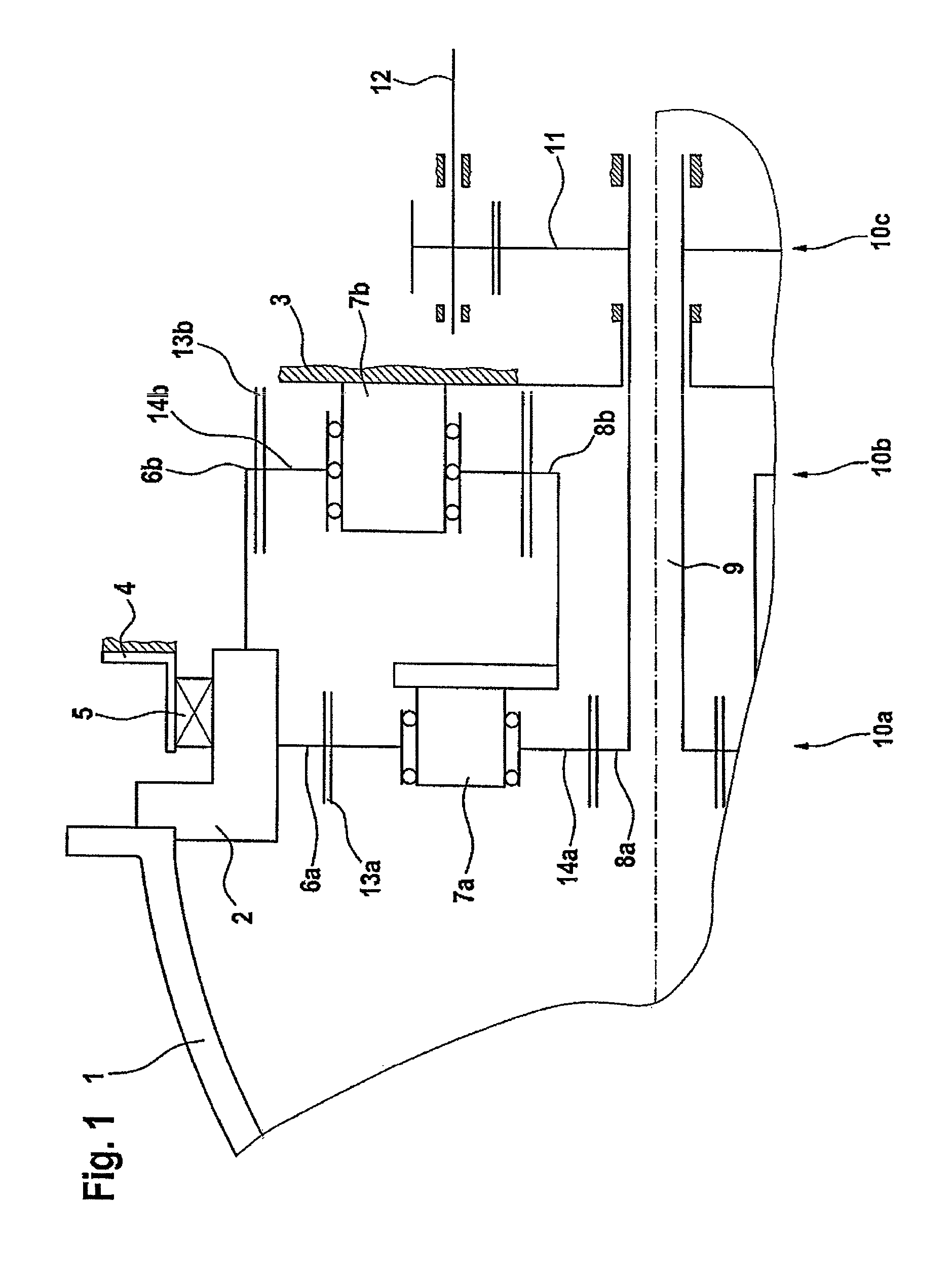
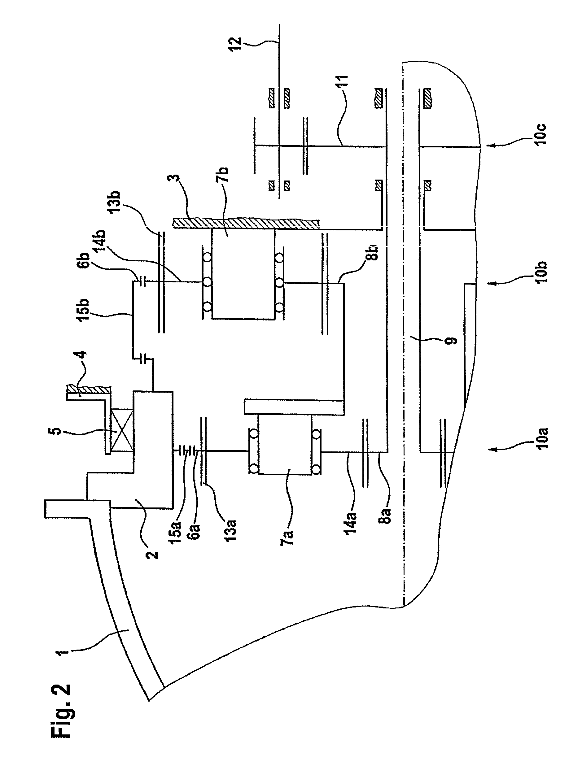
[0022]According to FIG. 1, a rotor hub 1 of a rotor (not shown in any more detail) is mounted on a connection ring element 2 on the transmission input side. The outer diameter of rotor hub 1 here approximately corresponds to the outer diameter of connection ring element 2 which, in turn, approximately corresponds to the outer diameter, or the outer dimensions, of a transmission housing 3 accommodating the transmission components. Transmission housing 3 is fixedly connected with a support structure (not shown in any more detail) of the nacelle at the top of a tower of a wind turbine generator system.

[0023]The connection ring element 2 on the input side of the transmission is rotatably supported at the fixed transmission housing 3 via a large roller bearing 5 by means of its outer race. The inner race of the large roller bearing 5, by contrast, receives the connection ring element 2.

[0024]The large roller bearing 5 fulfills the function of a moment bearing, wherein the input-side torq...


PUM


Abstract

A power-distributed wind turbine transmission for transmitting a torque generated by a rotor hub to an output pinion rotating with increased speed compared to the former to drive an electric generator, wherein at least two parallel-connected planetary stages are provided for power-distributed speed increase internal to the transmission, wherein further coupling of the rotor hub is carried out by means of a connection ring element on the input side of the transmission, which is rotatably supported by a large roller bearing at a fixed transmission housing, and which transmits the force flow in a power-distributed manner to the hollow gears of the parallel-connected planetary stages by means of cardan-like decoupling means formed thereon.

Description

FIELD OF THE INVENTION[0001]The present invention relates to a power-distributed wind turbine transmission for transmitting a torque generated by a rotor hub to a power-output shaft rotating at relatively higher speed compared to the former, for driving an electric generator, wherein at least two parallel-connected planetary stages are provided for power-distributed transmission within the transmission.BACKGROUND OF THE INVENTION[0002]In a wind turbine generator system of the type of interest here, in the power flow between a rotor converting the wind energy into a rotary motion and a generator transforming the rotary motion into electric energy, a transmission with a speed increase is arranged. Since the modules of the wind turbine generator system are mostly placed within a nacelle at the top of a tower, a transmission which is as compact as possible and has the lowest possible mass is desirable. This requirement is in conflict, however, with the tendency towards ever larger wind ...

Claims


Application Information

Patent Timeline
IPC IPC(8): F16H57/08
CPCF03D1/00F03D11/00F03D11/02F16H37/0833F05B2260/40311F16H1/22F16H1/227Y02E10/721Y02E10/722F03D80/00F03D15/00F03D80/70F03D15/10Y02E10/72F05B2240/50
Inventor BERGER, GUNTERBAUER, GERHARD
Owner ZF FRIEDRICHSHAFEN AG
Learn More