Continuous-wave laser

a laser and continuous wave technology, applied in the direction of laser details, basic electric elements, optical resonator shape and construction, etc., can solve the problem that none of these continuous wave raman lasers have incorporated intracavity frequency doubling, and provide any indication on how to achieve such intracavity frequency doubling

Active Publication Date: 2013-01-01
MACQUARIE UNIV
View PDF8 Cites 11 Cited by
  • Summary
  • Abstract
  • Description
  • Claims
  • Application Information

AI Technical Summary

Benefits of technology

[0080]In an arrangement of any one of the first to sixth aspects or alternative aspects, the length of the resonator cavity may be in the range of 10 mm to 2000 mm. In other arrangements the length of the resonator cavity may be in the range of 10 to 1500, 10 to 1200, 10 to 1100, 10 to 1000, 10 to 900, 10 to 800, 10 to 700, 10 to 600, 10 to 500, 10 to 400, 10 to 300, 10 to 200, 10 to 100, 10 to 90, 10 to 80, 10 to 70, 10 to 60, 10 to 50, 10 to 40, 10 to 30, 10 to 20, 50 to 1500, 50 to 1200, 50 to 1000, 50 to 900, 50 to 800, 50 to 700, 50 to 600, 50 to 500, 50 to 400, 50 to 300, 50 to 200, 50 to 100, 100 to 2000, 100 to 1500, 100 to 1000, 100 to 800, 100 to 600, 100 to 500, 100 to 400, 100 to 300, 100 to 200, 500 to 2000, 500 to 2000, 500 to 1500, 500 to 1250, 500 to 1200, 500 to 1100, 500 to 1000, 500 to 900, 500 to 800, 500 to 700, 500 to 600, 750 to 2000, 750 to 1500, 750 to 1250, 750 to 1200, 750 to 1100, 750 to 1000, 750 to 900, 750 to 800, 1000 to 2000, 1000 to 1750, 1000 to 1500, or 1000 to 1250. A feature of long resonator cavities (for example greater than 300, 400, or 500 mm) is that the laser will operate in multi-longitudinal mode which may enhance the stability of the laser.
[0183]In an arrangement of the fifteenth aspect, the method further comprises positioning the at least first and second reflectors, the laser gain medium, the Raman medium, and the nonlinear medium to provide a stable resonator cavity. The resonator may be stable when the laser medium is pumped by the pump beam to provide a stable continuous wave Raman laser when in operation.

Problems solved by technology

None of these continuous wave Raman lasers have incorporated intracavity frequency doubling, nor provided any indication on how such intracavity frequency doubling could be accomplished.

Method used


Image

  • Continuous-wave laser
  • Continuous-wave laser
  • Continuous-wave laser

Examples


example 1

Intracavity-Doubled Continuous Wave Raman Laser

Summary

[0439]Continuous wave operation at 588 nm of a diode-pumped, Raman-shifted (KGW), intracavity-doubled (LBO), Nd:GdVO4 laser is reported. The maximum cw output power at 588 nm was 320 mW when pumped with 18 W from a fibre-coupled diode at 808 nm. An efficient simple, diode end-pumped, intracavity doubled (LBO), Raman-shifted (KGW) Nd:GdVO4 laser is described representing a CW crystalline Raman laser-based yellow source.

Experiment

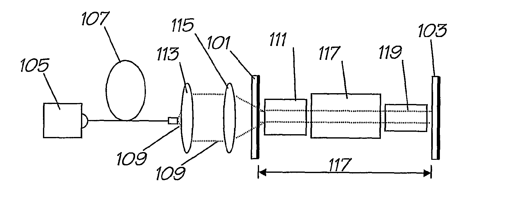
[0440]A plano-plano resonator showing the arrangement of the laser system of the present example is seen in FIG. 1. The resonator 100 was bound by a flat input mirror 101 2 mm thick, coated 85% T at 808 mm, HR (0.09% T) at 1064 nm, 0.4% T at 1176 nm and with 93% T at 588 nm, and for operation at 588 nm a flat output coupler 103 with the same coating. The pump source 105 was a 30 W fiber-coupled diode laser (φ=400 μm, NA˜0.22) operating at 808 nm with optical fibre 107 for delivery of the pump beam 109. The...

example 2

Intracavity Frequency-Doubled CW Self-Raman Laser

[0458]Intracavity frequency-doubled cw self-Raman laser based on a diode-pumped Nd:GdVO4 / KGW combination has been obtained, with the laser generating 704 mW in the yellow at 588 nm.

[0459]The configuration of the present arrangement of the Raman laser is illustrated in FIG. 6. The pump source 201 was a 30 W fiber-coupled 808 nm diode laser (φ=400 μm, NA˜0.22), imaged with unity magnification through the pump mirror 203 onto an AR-coated (1064-1200 nm) a-cut 0.3 at. % Nd:GdVO4 crystal 205 (3×3×10 mm). Quoted diode pump powers relate to powers incident on the laser crystal 205. Raman shifting was obtained using a KGW crystal 207 with dimensions of 5×5×25 mm, AR-coated for the near-infrared and cut and oriented for propagation along the Np axis with the plane of polarization parallel to Nm. KGW was selected for its superior thermal properties, good Raman gain coefficient and high damage threshold. Second harmonic generation (SHG) of the 1...

example 3

Self-Raman CW Laser

[0479]In this example, intracavity-doubled cw self-Raman laser operation is observed from a laser system based on a diode-pumped Nd:GdVO4 which generates 678 mW in the yellow at 586 m (with a diode-to yellow conversion efficiency of 4.2%) and 2 W cw at the first-Stokes at 1173 nm. Maximum cw powers at both wavelengths were limited by the effects of strong thermal lensing in the laser / Raman crystal. To explore the potential for generating higher cw powers, the laser was operated in quasi-cw mode (50% pump duty-cycle) to reduce the thermal loading of the crystal, whereupon 1.88 W maximum output power at 586 nm was obtained. To the best of the inventors' knowledge this is the first report of cw self-Raman laser operation in Nd:GdVO4 and efficient intracavity doubling of the first-Stokes field to the visible, and the highest output power of any self-Raman laser.

Experimental Set-Up

[0480]The Raman laser configuration is illustrated in FIG. 9. The resonator 300 was bound...


PUM


Abstract

A continuous wave Raman laser for producing visible laser output comprising: a resonator cavity; at least a first reflector and a second reflector said first and second reflectors being located at opposite ends of the resonator cavity; a laser gain medium located in the resonator cavity for generating a continuous wave fundamental beam which resonates within the resonator cavity when pumped by a pump beam from a pump source external to the resonator cavity; a solid Raman-active medium positioned in the resonator cavity for Raman shifting the fundamental beam to produce a continuous wave Raman beam which resonates within the resonator cavity; and a non-linear medium positioned in the resonator cavity for frequency converting the continuous wave Raman beam to a converted wavelength to produce a continuous wave converted beam.

Description

TECHNICAL FIELD[0001]The present invention relates to continuous wave lasers and in particular to continuous wave Raman lasers. The invention has been developed primarily for use as a continuous wave Raman laser providing output in the visible region of the optical spectrum and will be described hereinafter with reference to this application. However, it will be appreciated that the invention is not limited to this particular field of use.BACKGROUND OF THE INVENTION[0002]There has been a recent surge in interest for continuous-wave, solid-state yellow laser sources, for a diverse range of applications including ophthalmology, biomedicine, guide stars and visual display. Currently, CW dye lasers and krypton ion lasers offer CW output powers of up to 1 W. Recently, frequency doubled neodymium lasers have become available, typically producing 100 mW output at 563 nm wavelength. Among the recently reported approaches to demonstrating CW laser sources are a 40 mW, 575 nm frequency double...

Claims


Application Information

Patent Timeline
Patent Type & Authority Patents(United States)
IPC IPC(8): H01S3/30
CPCH01S3/1086H01S3/0014H01S3/08H01S3/08072H01S3/08086H01S3/0815H01S3/094053H01S3/09415H01S3/109H01S3/1611H01S3/1671H01S3/1673H01S3/1675H01S2301/02
Inventor DEKKER, PETERPASK, HELEN MARGARETPIPER, JAMES AUSTINSPENCE, DAVID JAMES
Owner MACQUARIE UNIV
Why Eureka
Try Eureka